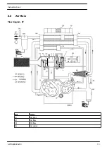
Explanation of arrows
Ref
Name
(1)
Air inlet
(2)
Air flow
(3)
Oil flow
(4)
Air outlet
Description
Two condensate traps are installed: one downstream of the intercooler (MTi) to prevent condensate from
entering compressor element (Eh) and one downstream of the aftercooler (MTa) to prevent condensate from
entering the air outlet pipe. The condensate traps are connected to Electronic Water Drains (EWDi and EWDa
respectively).
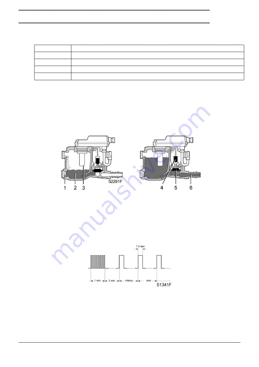
The condensate enters the electronic water drain via inlet (1) and accumulates in collector (2). A capacitive
sensor (3) continuously measures the liquid level. As soon as the collector is filled up to a certain level, pilot
valve (4) is activated and diaphragm (5) opens outlet (6), discharging the condensate. When the collector has
been emptied, the outlet closes quickly without wasting compressed air.
When the controller registers a malfunction, the red alarm LED starts flashing and the electronic drain valve
will automatically change to the alarm mode, opening and closing the valve according to a sequence as shown
below.
This condition continues until the fault is remedied. If the fault is not remedied automatically, maintenance
is required.
Instruction book
APFS998935v00
15
Summary of Contents for ZT-55
Page 1: ...CustomDesign Oil free Air Project 998935 Customer AIR SEP USA ZT 55 Instruction book ...
Page 2: ......
Page 13: ...General view Rear view Instruction book APFS998935v00 11 ...
Page 25: ...Typical example Drive motor M1 Instruction book APFS998935v00 23 ...
Page 57: ...4 2 Installation proposals Installation proposal ZT Pack Instruction book APFS998935v00 55 ...
Page 88: ......
Page 89: ......


