background image

Product Identification 

8

12ASL

Product Identifi cation

The identi

fi

 cation data of the machine are shown in the label placed on the 

control unit.

LOGO

Type:    ……………

Model: 

   ……………

Serial 

Number: 

  ……………

Year of manufacturing: 

……………

Capacity: 

   ……………

Voltage: 

   ……………

Power: 

   ……………

Use the above data both to order spare parts and when getting 

in touch with the manufacturer (inquiry). The removal of this 

label is strictly forbidden.

Machines may be updated or slightly modi

fi

 ed from an aesthetic point of view 

and, as a consequence, they may present different features from these shown, 

this without prejudicing what has been described herein.

2.1 Warranty 

Certifi cate

The warranty is valid for a period of 2 years on structural components, 1 year 

on hydraulic components and 90 days on wear parts starting from the date 

of purchase. This warranty does not include labor or shipping. The warranty 

consists of parts only. The warranty will come immediately to an end when 

unauthorized modi

fi

 cations, faulty assembly and improper use to the lift or parts 

of it are carried out. The presence of defects in workmanship must be veri

fi

 ed by 

Greg Smith Equipment Sales.

Summary of Contents for 12ASL

Page 1: ...Replace This With Cover PDF ...

Page 2: ...Revised 01 28 2020 Read this entire manual before operation begins Record below the following information which is located on the serial number data plate Serial No Model No Date of Installation ...

Page 3: ...ormation 5 Product Identification 8 Packing Transport Storage 10 Product Description 12 Technical Specification 14 Safety 22 Installation 26 Operation And Use 36 Maintenance 43 Troubleshooting 45 Parts List 48 Warranty 71 ...

Page 4: ...ions which need proper care Indicates prohibition Indicates a possibility of danger for the operators Indicates the direction of access for motor vehicles to the lift BOLD TYPE Important information WARNING before operating the lift and carrying out any adjustments read chapter 7 installation where all proper operations for a better functioning lift are shown ...

Page 5: ...fety Of The Lift Safety Of Lifted Vehicles The company is not liable for possible problems damage accidents etc resulting from failure to follow the instructions contained in this manual Only skilled technicians of AUTHORIZED DEALERS or SERVICE CENTERS AUTHORIZED by the manufacturer shall be allowed to carry out lifting transport assembling installation adjustment calibration settings extraordinar...

Page 6: ...n shall be forbidden This manual is an integral part of the lift it shall be given to the new owner if and when the lift is resold 1 2 Obligation In Case Of Malfunction In case of machine malfunction follow the instructions contained in the following chapters 1 3 Cautions For The Safety Of The Operator Operators must not be under the influence of sedatives drugs or alcohol when operating the machi...

Page 7: ...ial waste material and should be broken down into uniform parts and disposed of in compliance with current laws and regulations If the packing are not polluting or non biodegradable deliver them to appropriate handling station DECLARATION OF WARRANTY AND LIMITATION OF LIABILITY The manufacturer has paid proper attention to the preparation of this manual However nothing contained herein modifies or...

Page 8: ...w and as a consequence they may present different features from these shown this without prejudicing what has been described herein 2 1 Warranty Certificate The warranty is valid for a period of 2 years on structural components 1 year on hydraulic components and 90 days on wear parts starting from the date of purchase This warranty does not include labor or shipping The warranty consists of parts ...

Page 9: ...not specified or shown in these instructions contact your Dealer where the machine has been bought or the Manufacturer s Commercial Department Only skilled personnel who are familiar with the lift and this manual shall be allowed to carry out packing lifting handling transport and unpacking operations ...

Page 10: ...cess covers No 2 drive on ramps 2 front wheel stops and 4 hose protective covers if the lift is ordered for on floor installation If requested optional accessories are available to satisfy each customer s requirements 3 2 Lifting And Handling When loading unloading or transporting the equipment to the site be sure to use suitable loading e g cranes trucks and hoisting means Be sure to hoist and tr...

Page 11: ... well as its considerable weight and size make it difficult and hazardous 3 4 Delivery And Check Of Packages When the lift is delivered check for possible damages due to transport and storage verify that what is specified in the manufacturer s order confirmation is included In case of damage in transit the customer must immediately inform the carrier of the problem Packages must be opened paying a...

Page 12: ... in figure 2 the lift is composed of two runways P1 1 and P2 2 with two rolling jacks 3 anchored onto the floor by means of two bases 4 Runways are linked to the base by means of a scissors lifting system The lifting system of each runway is composed of scissor arms 5 and a hydraulic cylinder 6 Turntable recess covers 7 are supplied with the lift in case for non alignment purposes The lifting and ...

Page 13: ... cylinder The hydraulic system is protected by a max pressure valve thus preventing pressure from exceeding the maximum fixed safety limit The synchronization of the platforms is carried out by a master slave circuit Lifting and lowering motion on the lift is controlled by the push buttons on the control panel Whenever the lift has to be lowered to the ground and the lowering button is pressed the...

Page 14: ... 120psi Noise Level 80 dB A 1m Working Temperature 14 F 104 F Average Weight Of Package 5000lbs 5 2 Electric Motor Type ML90L2 Specification 220V 1Ph Power 2 2 KW N Poles 2 Speed 2800 rpm Motor enclosure type B14 Insulation class IP 54 Motor connection must be carried out referring to the attached wiring diagrams Fig 6 The motor rotation is shown by the label placed on the motor cover Before using...

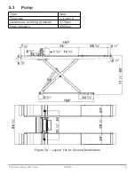
Page 15: ...Technical Specification 15 12ASL 5 3 Pump Type Gear Flow rate 1 3 cm3 g Continuous working pressure 3770psi Peak pressure 4060psi Figure 3A Layout For In Ground Installation ...

Page 16: ...Technical Specification 16 12ASL Figure 3B Layout For On Ground Installation ...

Page 17: ...Technical Specification 17 12ASL 5 4 Hydraulic Unit The power unit is equipped with Figure 4 Hydraulic Power Unit ...

Page 18: ...ANDARDS FEATURES VALUE ASTM D 1298 Density 20 C 0 8 kg l ASTM D 445 Viscosity 40 C 32 cSt ASTM D 445 Viscosity 100 C 5 43 cSt ASTM D 2270 Viscosity index 104 N ASTM D 97 Pour point 30 C ASTM D 92 Flash point 215 C ASTM D 644 Neutralization number 0 5 mg KOH g CHANGE HYDRAULIC OIL AT A HALF YEAR INTERVALS FOR THE FIRST TIME USE CHANGE THE OIL IN THREE MONTHS ...

Page 19: ...Slave platform cylinder P2 9 Lowering speed control 3 Leveling cock N O normally open 10 Motor 4 Leveling cock N C normally close 11 Gear pump 5 Pressure gauge 12 Emergency hand pump 6 Non return valve 13 Oil filter 7 Pressure overload valve 14 Parachute valve optional Figure 5 Hydraulic Plan ...

Page 20: ...ifting button M Motor 2 2KW 1PH SB2 Lowering final lowering button ST Thermal relay SB3 Safety engaging button KM Contactor AC 220V SQ1 Top limit switch YV1 Lowering solenoid valve 220V SQ2 Safety height limit switch QV1 Safety air valve 220V Figure 6 Electrical Diagram 220V 1PH ...

Page 21: ... Figure 7 Pneumatic Plan Regulated pressure must be set between 90psi 120psi It is recommended to install a filter regulator lubricator FRL to maintain the integrity of the electronic air valve s and rolling jack air hydraulic pump s ...

Page 22: ...es to people vehicles or objects resulting from an improper or unauthorized use of the lift For operator and people safety the safety area shown in Figure 8 must be vacated during lifting and lowering The lift must be operated only from the operator s control site as shown Operator s presence under the vehicle during working is only admitted when the vehicle is lifted and platforms are not running...

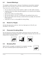
Page 23: ...t in neutral and the parking brake put on Be sure only authorized vehicles are lifted without exceeding the maximum lifting capacity Verify that no one is on the platforms during lifting 6 2 Risks For People All risks the personnel could run due to an improper use of the lift are described in this section 6 3 Personnel Crushing Risks During lowering of runways and vehicles personnel must not be wi...

Page 24: ...emove all oil spills 6 7 Electrocution Risks Avoid use of water steam and solvent varnish jets in the lift area where electric cables are placed and in particular next to the electric panel 6 8 Risks Resulting From Improper Lighting Make sure all areas next to the lift are uniformly lit according to local regulations 6 9 Risks Of Breaking Component During Operation Materials and procedures suitabl...

Page 25: ...le in close proximity of the machine 6 11 Risks During Vehicle Lifting To avoid overloading and possible breaking the following safety devices have been installed A maximum pressure valve placed inside the hydraulic unit to prevent excessive weight A special design of the hydraulic system in case of a pipeline failure to prevent the lift suddenly lowering The maximum pressure valve has been preset...

Page 26: ...d Safety at Work regulations with respect to minimum distance to wall or other equipment escapes and the like must be observed 7 2 Lighting Lighting must be carried out according to local regulations for the place of installation All areas next to the lift must be well and uniformly lit 7 3 Installation Foundation The lift must be placed on a minimum of 3000psi concrete at 6 in depth If a floor co...

Page 27: ...rete must be adequately cured for a 21 day minimum 7 4 Lift Positioning Unauthorized persons are not allowed to enter during assembly Transport each platform lifting system to the location or the recessed pit using hoisting device with a load capacity of 1 6 tons at least To prevent the platform from dropping during transport it should be lifted according to its center of gravity Place the control...

Page 28: ...Figure 16 route hydraulic lines referring to the letters shown on them through the pipe into the prepared foundation Connect hydraulic hoses to the fittings Tighten thoroughly When routing the hydraulic hoses make sure that the hose is clear of any moving part make sure to keep the hoses and fittings clean from debris Failure to do so may result in hydraulic line failure which may result in damage...

Page 29: ... 6 Connect the pneumatic lines pre assembled on the runways to the safety air valve in the control unit Connect the pneumatic system of the lift to the pneumatic supply at site Check the pneumatic control operations for proper performance 7 7 Make The Electrical Connection To Control Unit The hookup work must be carried out by a qualified electrician Make sure that the power supply is right Make s...

Page 30: ...otor plate Make sure the electrical connections are in compliant with diagrams Figure 5 Make sure there is no leakage or expansion in hydraulic lines and pneumatic lines Make sure the lift is anchored to the ground Make sure the working area is free of people and objects Grease rollers placed under platforms and on the bases Verify the control unit is powering on Pour oil in the tank 3 5 to 5 Gall...

Page 31: ...the runway P1 completely Raise the runway again until it reaches the maximum height Turn off the leveling cutoff valve N O 1 Turn on the leveling cutoff valve N C 2 Press the lifting button to raise the runway P2 the slave runway drivers side until it reaches the maximum height More oil may need to be added Press the lowering button to lower the runway P2 completely Repeat raise and lower on the r...

Page 32: ...e full holding power do not ream the hole or allow drill to wobble After drilling remove dust thoroughly from each hole using compressed air or wire brush Assemble the washers and nuts on the anchors then tap into each hole with a hammer until the washer rests against the bases Verify that both the runways are leveled horizontally by using a level If necessary adjust in the following way below unt...

Page 33: ...ossible to adjust it via the nuts on the switch Tighten the nuts after adjustment Fix the switch cover with the supplied screws 7 10 2 Safety Height Limit Switch Place the lift at a desired height 16 from the floor is suggested Mount the switch 2 into the threaded holes on the arm using the included screws Lower the lift by pressing the main down button so the safety height limit switch shuts off ...

Page 34: ...his procedure observe all operating components and check for proper installation and adjustment DO NOT attempt to raise a vehicle until a thorough operation check has been completed Be sure the lift is fixed to the ground and all anchor bolts tightened Carry out two or three complete cycles of lifting and lowering and check The safeties for proper operation Proper oil level in the tank No leakage ...

Page 35: ...SL 7 13 Checking With Load Carry out two or three complete cycles of lifting and lowering and check Repeat the 7 12 section Check for noises during lifting and lowering If the runways are not level repeat the 7 8 section ...

Page 36: ...ade to work on or near the vehicle and two runways MUST be at equal height from the floor when resting on the safeties Never leave the lift in an elevated position unless the safeties are engaged If an anchor bolt becomes loose or any component of the lift is found to be defective DO NOT USE THE LIFT until repairs are made Do not allow the electric control unit to get wet 8 1 Operation Of Runway F...

Page 37: ...hat the lift is in bleeding ADJ process shows the safety release time which is preset by the manufacturer if no special request When lights it shows that the play detector is working if it is ordered with the lift BEEPER 3 LIFTING BUTTON UP 4 When pressed the electric circuit for the lift operates the motor and hydraulic circuit to raise the lift SAFETY ENGAGING BUTTON 5 When pressed the lowering ...

Page 38: ...he leveling cock N C is off Press the lifting button to lift the vehicle to the required height 8 1 2 Standing To rest the lift in standing position at the desired height release the lifting button Press the safety locking button to engage the safeties Always ensure that safeties are engaged before any attempt is made to work on or near the vehicle Always ensure that two runways MUST be in equal h...

Page 39: ...ering button again until the lift is lowered completely A beep sound is heard during the last travel Be sure to extract the platform extension fully before lowering the lift to the pit The manufacturer will not be responsible for any damage of the lift because of failure to do so 8 2 Operation Of The Rolling Jack The rolling jack is operated by an air hydraulic pedal pump supplied with the lift Fi...

Page 40: ...air hose to the compressed air FLUID PORT 5 It is to be connected with the hydraulic hose from the pump to the jack cylinder 8 2 1 To Raise The Jack Beam Never raise the rolling jack beyond the rated height The manufacturer will not be responsible for the damage because of the incorrect operation Check to be sure the hydraulic hose and the air hose are connected properly Check to be sure the oil i...

Page 41: ...m is lowered completely 8 3 Runway Leveling Warning engage the mechanical safety locks when the vehicle is left on the runways for long periods ex during the night During this procedure DO NOT attempt to raise lift with any load After a period of service due to natural loss of the oil or trapped air in the hydraulic line it could be possible that the runway P2 the slave runway is lower than the ru...

Page 42: ...essing the emergency button 3 on the solenoid air valve in the control unit Unloosen the emergency screw 2 anti clockwise to lower the lift Tightening or loosening the screw can reduce or increase the lowering speed Re tighten the emergency screw by screwing it clockwise after lowering the lift completely Tip when a mechanical safety is released it is advised to use a carton board to put between t...

Page 43: ...and hydraulic equipment Exploded views with all data necessary for spare parts ordering List of possible faults and relevant solutions Before carrying out any maintenance or repair on the lift disconnect the power supply padlock the general switch and keep the key in a safe place to prevent unauthorized persons from switching on or operating the lift 9 1 Ordinary Maintenance The lift has to be pro...

Page 44: ...ning and check fixing bolts for proper tightening Safety system check safety devices for proper operation Every 6 months Oil check oil for contamination or aging Contaminated oil is the main reason for failure of valves and shorter life of gears pumps empty the oil tank and change the hydraulic oil Every 12 months General check verify that all components and mechanisms are not damaged Electrical s...

Page 45: ... when UP button is pressed The motor direction of rotation is not correct Interchange the phases on the main switch The oil in the hydraulic unit is not sufficient Add some hydraulic oil The UP button is faulty Check UP button and connection for proper operation Replace if needed The lowering solenoid valve does not close Check and clean if dirty or replace if faulty The emergency screw of lowerin...

Page 46: ...ed and check the magneto for damages replace if disconnected or burnt The DOWN button is faulty Check the button and connection for proper operation Replace if needed The lift does not stop at the safety height The safety height limit switch is not adjusted correctly or it is faulty Adjust or change the limit switch The electric board is faulty Replace electric board The electric board is not oper...

Page 47: ...does not lift or lower smoothly Leakages or presences of air into hydraulic circuit Bleed the hydraulic system The motor does not stop when reaching it maximum height The maximum height limit switch does not work Check the limit switch and replace if needed The lift does not lift or lower smoothly Leakages or presences of air into hydraulic circuit Bleed the hydraulic system The pump filter is dir...

Page 48: ...tration Lift Parts List Item Part No Description Qty 1 8250DXL 100000 Runway P1 1 2 8250DXL 200000 Runway P2 1 3 8240D17000 Control unit 1 4 0206013 Screw M4X12 GB T818 1 5 0206017 Screw M4X25 GB T818 1 6 0505018 Safety position limit switch 8108 1 ...

Page 49: ...5 Screw M14X25 GB T5781 4 19 8200TX 007100 Short ramp 2 20 J07Q Jacking beam HJ 75B 2 21 8200TY 800002 Turntable recess cover 2 22 8240TXKL 4G Rear beam 1 23 0204008 Self locking nut M16 GB T889 1 8 24 8200B6 800012 Ramp pin 4 25 J62B400000 Long ramp for on ground installation 2 26 0201130 Screw M16X40 GB T5783 12 27 0208011 Washer D 16 GB T93 12 28 0205020 Washer D 16 GB T97 1 12 29 8240B 008640 ...

Page 50: ...1 824 110000G Base 1 2 824 100003 Lower shaft 2 3 0209025 Screw M8X12 GB T79 6 4 0210018 Self lubricated bush 3055 2 5 8250 02 01 17 Cylinder lower shaft 1 6 0210028 Self lubricated bush 3560 6 7 8250 120 00 Master hydraulic cylinder 1 8 8250 06 03 Lower safety rack 1 9 0207043 Screw M6X10 GB T973 1 ...

Page 51: ...250DXL 140000 P1 platform assembly 1 23 0209010 Screw M6X10 GB T78 2 24 GXQ 61X5 5 Hose relief ring 61X5 5 1 25 824 100001G Nylon slider 2 26 824 130000G Outer scissor arm 1 27 824 100004 Middle shaft 1 28 8250 02 26 Spacer 2 29 0209012 Screw M8X12 GB T78 2 30 0210080 Self lubricated bush 4055 4 31 8250 18 Shim 2 32 ZJJ3 17 Shim 10 33 0205025 Teethed washer D 30 GB T858 2 34 0204015 Nut M30 GB T61...

Page 52: ...43 0212007 Seeger D 32 GB T894 1 2 44 0309027 O ring 38X3 1 2 45 0309012 O ring 120X3 1 1 46 0310019 Seal 67X77X6 1 47 0305006 Guide ring 67X25X2 5 1 48 0311013 Scraper 67X75X5 1 49 GJ350 120A 2 Cylinder guiding cover 1 50 0312007 Gasket 120X95X22 4 1 ...

Page 53: ...tion Qty 1 824 111000 Front base 1 2 ZJJ3 0103 U connection rod 2 3 824 112000 Rear base 1 4 824 110001 Wheel guide 2 5 0204032 Nut M16 GB T6172 1 4 6 0207022 Screw M10X20 GB T819 1 4 7 0201180 Screw M16X85 GB T5780 4 8 0201103 Screw M16X50 GB T5781 10 9 0203025 Nut M16 GB T6170 10 ...

Page 54: ...s List Item Part No Description Qty 1 825DXL 141000 Platform 1 2 8250 000812 Turntable recess base plate 1 3 0207038 Screw M12X20 GB T70 3 6 4 8240B4 03150A Spacer 2 5 8240B4 031501 Movable spacer 2 6 8240C4 031501 Movable spacer 3 7 0202032 Screw M6X16 GB T70 1 2 8 824TX 143000 Cover 1 ...

Page 55: ...79 8 17 0205008 Washer D 8 GB T97 1 12 18 0206037 Screw M8X25 GB T70 2 6 19 0202040 Screw M8X16 GB T70 1 6 20 824 140007 Guide fastening plate 2 21 0203012 Nut M20 GB T6170 6 22 8240B4 800011 Special screw M20X70 6 23 825D 145100 Base plate 1 24 J63A332000 Roller gasket 8 25 0206032 Screw M6X16 GB T818 16 26 825D 142001 Slipping plate 1 27 824B 142200 Stop pin 2 28 0207036 Screw M8X20 GB T70 3 2 2...

Page 56: ...1 2 824 100003 Lower shaft 2 3 0209025 Screw M8X12 GB T79 4 4 0210018 Self lubricated bush 3055 2 5 8250 02 01 17 Cylinder lower shaft 1 6 0210028 Self lubricated bush 3560 2 7 8250 100 00 Slave hydraulic cylinder 1 8 8250 06 04 Lower safety rack 1 9 0207043 Screw M6X10 GB T973 1 10 0306010 Air locking cylinder 32X23 1 ...

Page 57: ...0209010 Screw M6X10 GB T78 2 24 GXQ 61X5 5 Hose relief ring 61X5 5 1 25 824 100001G Nylon slider 2 26 824 130000G Outer scissor arm 1 27 824 100004 Middle shaft 1 28 8250 02 26 Spacer 2 29 0209012 Screw M8X12 GB T78 2 30 0210080 Self lubricated bush 4055 4 31 8250 18 Shim 2 32 ZJJ3 17 Shim 10 33 0205025 Teethed washer D 30 GB T858 2 34 0204015 Nut M30 GB T6172 1 2 35 824 120000G Inner scissor arm ...

Page 58: ... Description Qty 44 0212007 Seeger D 32 GB T894 1 1 45 0312003 Gasket 100X75X22 4 1 46 0309027 O ring 38X3 1 1 47 0309079 O ring 100X3 1 GB1235 1 48 0305006 Guide ring 50X25X2 5 1 49 0310015 Seal 50X60X6 1 50 0311010 Scraper 50X58X5 1 ...

Page 59: ...Qty 1 J04A030002 Top cover 1 2 0206059 Screw M4X8 6 3 0508330 Guide DZ47 L 60mm 1 4 0508330 Guide DZ47 L 45mm 1 5 0507367 CPU board 102 1 1 6 0504016 Fuse 1A 5X20 3 7 0206058 Screw M5X10 6 8 0510380 Ground decal 2 9 0206019 Screw M4X6 GB T818 10 10 0508017 Cable relief GM 2314 8 11 J04A110001 Support 1 ...

Page 60: ... GB T818 2 24 3002002009 Cable holder 1 25 0508302 Holder HDB 16A 4 26a 0501066 Breaker DZ47 63 3P D16A For 400V 380V 3Ph 1 26b 0501074 Breaker DZ47 63 2P D32A For 230V 220V 1Ph 1 27 0501001 AC contactor CJX2 1210 220V 1 28 3054503904 Back cover 1 29 0306177 Solenoid air valve G1 4 3V210 08 220V 1 30 0205001 Washer D 3 GB T97 1 2 31 0208001 Washer D 3 GB T93 2 32 0203001 Nut M3 GB52 2 33 J04A03100...

Page 61: ...Parts List 61 12ASL Hydraulic Power Unit Parts Illustration ...

Page 62: ...509092 Motor 220V 60Hz 1PH 2 2KW 1 14 BZ ZT24 Motor joint 1 15 0209042 Screw M6X8 GB T80 1 16 0303063 Union 1 4 1BT 04SP 1 17 0307041 Leveling cutoff cock 1 4 BKH224 DN06 G1 4 2 18 0305054 Pressure gauge LA 60X400 1 19 0303031 90 union 1 4 1T9 04SP 1 20 0305001 Plug ZBJ22 007 QD07 2 21 BZ W YL Interface block 1 22 0203004 Nut M6 GB52 4 23 0213045 Double screw bolt M6X120 GB T901 4 24 0309019 O rin...

Page 63: ...et 1 39 0313001 Washer BS A13 70 For 1PH motor 1 40 0303002 90 union 1 4 1BT9 04SP 1 41 0306067 Union Φ10 ZG1 4 1 42 BZ G14X200 Oil return pipe 1 43 0303060 Union 1T 04SPL 1 44 BZ HC2 0 Startup valve For 1PH motor 1 45 BZ HC 6 Seal Φ16XΦ9X2 5 For 1PH motor 1 46 BZ HC2 1 Valve body For 1PH motor 1 47 BZ HC 2 Valve piston For 1PH motor 1 48 BZ HC2 3 Valve pin For 1PH motor 1 49 BZ HC2 4 Spring For 1...

Page 64: ...adaptor assembly 2 2 0202020 Screw M5X8 GB T70 1 2 3 J07K220000 Lifting arm 2 4 0212004 Seeger D 25 9 5 HJ RG 10 4 Shaft 1 6 J07K210000 Beam 1 7 0206031 Screw M6X10 GB T818 2 8 0215021 Greaser 8X1 1 9 HJ 63 0 Jack hydraulic cylinder unit 1 10 0211003 Seeger D 19 4 11 0210009 Bush SF 1 2525 4 12 HJ RG 19 Cylinder upper shaft 1 ...

Page 65: ...1 26 HJ RG 10 3 Shaft 1 27 J07K400000 Inner scissor arm 1 28 J07K300000 Outer scissor arm 1 29 0215016 Handle knob M8X25 1 30 HJ RG 08 0 Safety release handle 1 31 HJ SB 19 3 Spring 1 32 0215038 Steel ball D 8 1 33 0209010 Screw M6X10 GB T78 1 34 HJ RG 09 0 Safety hook 1 35 HJ RG 10 1 Shaft 1 36 0210066 Bush SF 1 2512F 4 37 HJ RG 10 2 Central shaft 1 38 0301052 Air hydraulic pedal pump 800CC 1 39 ...

Page 66: ...5007 Guiding ring 30x10x2 5 1 53 0311005 Scraper 30X38X5 6 5 1 54 HJ 75 4 Cylinder shaft 1 55 0309091 O ring 45X2 65 2 56 Z23A313002 Outer threaded bush 2 57 0212034 Seeger D 42 2 58 Z23A313001 Inner threaded bush 2 59 0212035 Seeger D 32 2 60 Z23A313100 Pad support 2 61 Z23A313202 Rubber pad 2 62 0202032 Screw M6X16 GB T70 1 2 63 Z23A601200 Adaptor extension H80 By special request 2 64 Z23A601300...

Page 67: ... No Description Qty 1 BZ W4LY Hydraulic power unit 1 2 8250 120 00 Master hydraulic cylinder 1 3 8250 100 00 Slave hydraulic cylinder 1 4 0303063 Union 1BT 04SP 3 5 0303003 90 degree union 1BT9 04SP Y 1 6 0303065 Union 1B 04 2 7 0303021 Tee union AB 04 1 8 ZZ1200 Hydraulic hose 1 4 L 1200 1 ...

Page 68: ...14 0306067 Union Φ10 ZG1 4 1 15 0306109 PU hose Φ10XΦ6 5X4900C 1 16 HJ 63 0 Jack hydraulic cylinder 1 17 0301052 Air hydraulic pedal pump 800CC 1 18 ZJ380 PU hydraulic hose L 380 1 19 ZJ700 Hydraulic hose L 700 1 20 BZ 720B 0401 Bolt 1 21 BZ GZ 002 Screw 1 22 0303065 Union 1B 04 1 23 0303027 Bolt 720B 04 1 24 0313001 Washer BS A13 70 6 25 0305001 Plug ZBJ22 007 QD07 1 26 0306112 Quick union Φ8 G1 ...

Page 69: ...s Illustration Pneumatic Line Parts List Item Part No Description Qty Remark 1 0306190 Solenoid air valve DC24V 1 2 0306010 Air safety release cylinder 32X23 2 3 0306086 Silencer 1 4 1 4 0306025 Tee quick union 6 1 5 0306041 Quick union 6 1 ...

Page 70: ...nion 6 1 4 1 Optional 14 0306095 Rilsan hose 6X4 L 850 1 Optional 15 0306121 90 degree quick union 6 1 Optional 16 0206015 Screw M4X16 for fixing the union GB T818 1 Optional 17 0306095 Spiral rilsan hose 6X4 L 4000 1 Optional 18 0306082 Rotation 90 degree union 6 1 4 1 Optional 19 0306192 Switching valve VMS 114 1 Optional 20 8250N61 810002G Special nut 2 Optional 21 8250N61 810001G Union 1 Optio...

Page 71: ...isuse negligence carelessness of operation or normal wear and tear In addition this warranty does not cover equipment when repairs or alterations have been made or attempted to the Manufacturer s products THIS WARRANTY IS EXCLUSIVE AND IS LIEU OF ALL OTHER WARRANTIES EXPRESSED OR IMPLIED INCLUDING ANY IMPLIED WARRANTY OR MERCHANTABILITY OR ANY IMPLIED WARRANTY OF FITNESS FROM A PARTICULAR PURPOSE ...

Reviews: