27
R. Install electrical system
Connect a power source matching the requirement of the Power Unit.
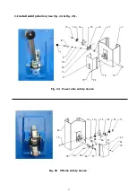
Note: 1. Install the limit switch
2. For the safety of operators, the ground wire must be used.
Single phase motor
(See Fig. 38).
1.
Connecting the two power supply lines (active wire
L
and neutral wire
N
) to
terminals
L1, L2
of AC contactor respectively.
2.
Connecting the two motor wires to
T1, T2
terminals of AC contactor
3.
Connecting
terminal A2
to terminal
L2
of AC contactor.
4.
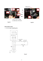
Connecting the limit switch: Removing the wire of connecting terminal
4#
of
control button and
A1
of AC contactor firstly
(See Fig. 39)
, then connecting
wire
12#
(brown wire)
of limit switch with terminal
4#
of control button and
connecting wire
11#
(blue wire)
with terminals
A1
of AC contactor respectively.
Connecting the earth wire (yellow and green wire) of limit switch to the earth wire
terminal on the motor.
(See Fig. 40)
.
5.
Connecting the terminal 3# on the control button to the terminal L1 on the AC
contactor.
Fig. 38
Summary of Contents for Atlas PV-10HPX
Page 1: ...1 Model PV10PX Revised 05 25 2021 ...
Page 10: ...10 D Install parts of extension columns See Fig 16 Fig 16 24 26 20 42 25 37 41 ...
Page 18: ...18 K Raise the carriages up by hand so they are locked at the same level See Fig 26 Fig 26 ...
Page 22: ...22 Install power unit See Fig 30 Fig 30 ...
Page 30: ...30 IV EXPLODED VIEW Model 211SAC Fig 43 ...
Page 38: ...38 4 5 POWER UNIT EXPLODED VIEW 220V 60Hz Single Phase Fig 48 ...


