REV. 01 2012
18 / 35
6.4
BALANCING MODES
During spinning, do not raise the wheel guard or press STOP button, do not
press the brake pedal. The spin cannot be completed and the error information
will be shown on the screen.
A spin can be performed by pressing START button or closing the wheel guard
if START BY LOWERING GUARD is enabled.
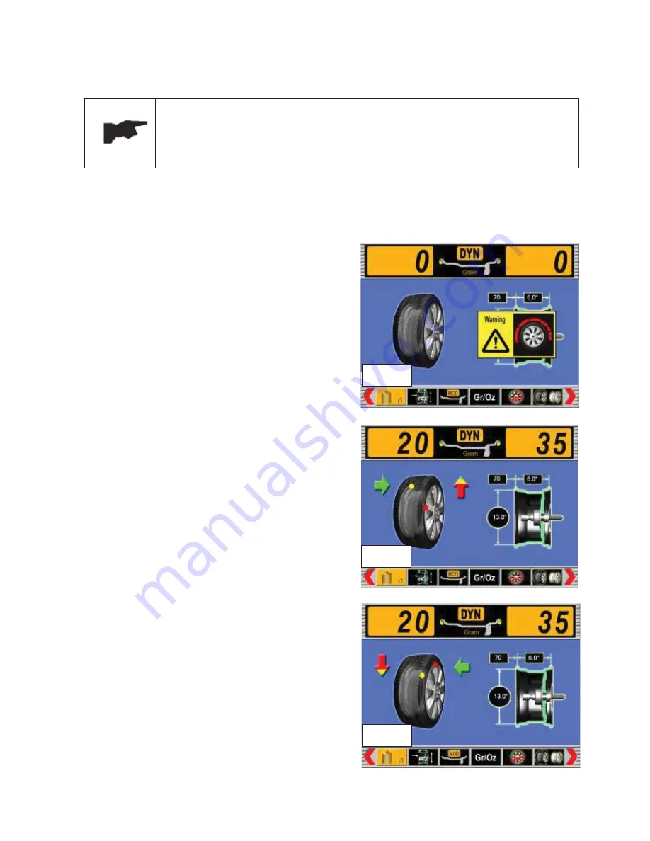
6.4.1 DYNAMIC MODE
The dynamic mode is used for most passenger and light truck wheels using the most common location
for corrective weights. Clip-on weights are placed on the inner and outer sides of the rim.
x
Select DYNAMIC mode.
x
Measure and set the wheel dimensions
automatically or manually.
x
Start a spin.
x
After the spin is completed, the unbalanced
amounts for both inner side and outer side of
the rim will be shown on the screen (ref. fig. 22
and 23).
6.4.1.1
CORRECTION OF INNER SIDE (ref. fig.
22)
x
Following the arrow direction, rotate the wheel
slowly by hand until the yellow dot on the inner
side moves to the 12 o
’
clock position, and the
arrow changes to be green color and points to
the 12 o
’
clock position.
x
Clip the correct weights on the position (12
o
’
clock position) for correction.
6.4.1.2
CORRECTION OF OUTER SIDE (ref. fig.
23)
x
Following the arrow direction, rotate the wheel
slowly by hand until the red dot on the outer
side moves to the 12 o
’
clock position, and the
arrow changes to be green color and points to
the 12 o
’
clock position.
x
Clip the correct weights on the position (12
o
’
clock position) for correction.
Fig. 21
Fig. 22
Fig. 23
Summary of Contents for WB55
Page 1: ......
Page 35: ...REV 01 2012 35 35 CHAPTER 12 ELECTRIC DIAGRAM...


