background image

6

MAKING THE ELECTRICAL 
CONNECTIONS

Warning:

 The power should have already 

been disconnected.  Follow the steps below to 
connect the fan to your household wiring. Use 
the wire nuts supplied with your fan. Secure 
the wire nuts with electrical tape. Make sure 
there are no loose strands or connections.

NOTE:

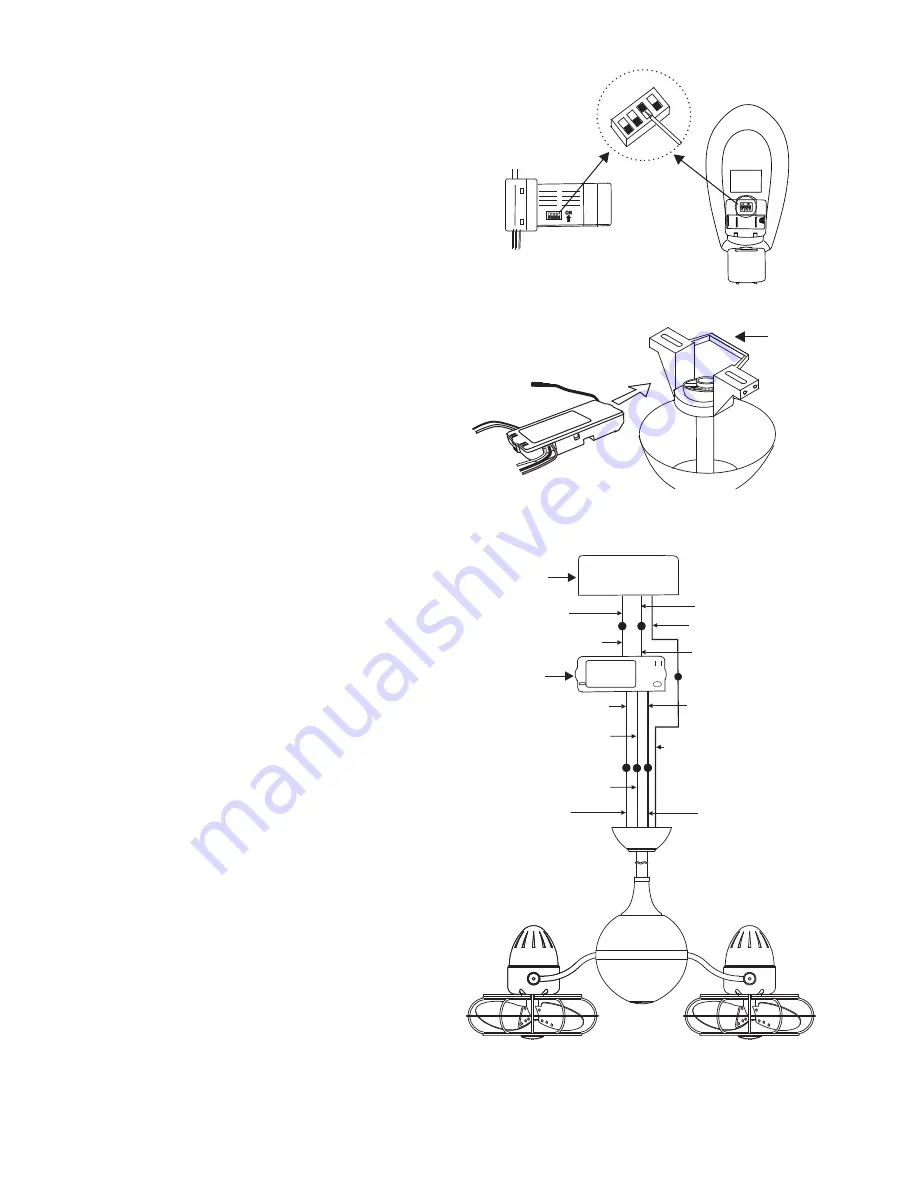
 The Hand Held Remote Control units 

included with your ceiling fan are equipped 
with 16 code combinations to prevent possible 
interference from or to other remote units. The 
frequency switches on your Receiver and 
Transmitter units have been preset at the 
factory. Please re-check to make sure the 
switches on both units are set to the same 
positions. The frequency settings should be 
changed only in case of interference or if a 
second or more remote controlled ceiling fans 
are installed in the same room. Any code 
combination will operate the ceiling fan and 
light as long as the Receiver and Transmitter 
units are set to the same codes. (Fig. 9)

1. Insert Receiver into Hanger Bracket with 
the flat side of the Receiver facing the ceiling. 
(Fig. 10)

2.  Motor to Receiver Electrical Connections:  
Connect the WHITE wire from the fan to the 
WHITE wire marked "TO MOTOR N" from the 
Receiver.  Connect the BLACK wire from the 
fan to the BLACK wire marked "TO MOTOR 
L" from the Receiver. Connect the BLUE wire 
from the fan to the BLUE wire marked "Light" 
from the Receiver. Proceed to secure all wire 
connections with the plastic wire nuts 
provided. (Fig. 11)        

Note:

 Fan must be installed from a maximum 

distance of 40 feet from the transmitting unit 
for proper signal transmission between the 
transmitting unit and the fan's receiving unit.

3.  Receiver to House Supply Wires Electrical 
Connections: Connect the WHITE wire 
(Neutral) from the outlet box to the WHITE 
wire marked "AC in N" from the receiver. 
Connect the BLACK wire (Hot) from the outlet 
box to the BLACK wire marked "AC in L" from 
the receiver. Secure all wire connections with 
the plastic wire nuts provided. (Fig. 11) 

Figure 9

Figure 10

Figure 11

Receiver

Hanger 
bracket

WHITE (NEUTRAL)

WHITE (NEUTRAL)

GREEN OR BARE
COPPER (GROUND)

WHITE ("AC IN N")

WHITE ("TO MOTOR  N")

GROUND-
(GREEN)

(3 GROUND WIRES
 ON CEILING FAN) 

OUTLET BOX

BLACK (HOT)

BLACK ("AC IN L")

BLACK ("TO MOTOR  L")

RECEIVER

BLUE (LIGHT)

BLUE (LIGHT)

BLACK (MOTOR)

Summary of Contents for Acqua

Page 1: ...E THESE INSTRUCTIONS Acqua Ceiling Mounted Rotational Fan FAN RATING AC 220V 50Hz Please do not use any electric or battery powered tools in the assembly and installation of this or any Matthews Fan Company product ...

Page 2: ... are metal and accompanied by safety cages see Diagram e i To reduce the risk of injury to persons install fan so that blades are at least 7 0 Ft above the floor in the US and 8 3 Ft 2 5 M above the floor in Canada If blades are metal and accompanied by decorative cages See Diagram e ii or unguarded wooden blades See Diagram e iii To reduce the risk of injury to persons install fan so that blades ...

Page 3: ...Canada to satisfy CSA requirements at least 8 3 Ft 2 5 M above the floor and all objects in room if safety cages are utilized 10 0 Ft if safety cages are not utilized In the US to satisfy UL requirements at least 7 0 Ft above the floor and all objects in room if safety cages are utilized 10 0 Ft if safety cages are not utilized 9 To reduce the risk of personal injury do not bend blades or any othe...

Page 4: ...ket ANGLED CEILING MAXIMUM 24 ANGLE 11 To reduce the risk of personal injury install the supplementary mounting means and use only the hardware provided with the fan 12 Warning TO REDUCE THE RISKS OF FIRE ELECTRIC SHOCK OR INJURY TO PERSONS OBSERVE THE FOLLOWING A Use this unit only in the manner intended by the manufacturer If you have any questions contact the manufacturer B Before installing se...

Page 5: ...e top of the fan motor through the coupling cover canopy cover and canopy and then through the ball downrod Fig 7 NOTE Make sure that coupling cover has at least 1 8 to 1 4 clearance between it and fan motor assembly If this clearance is not given the fan will not rotate 6 Align the holes at the bottom of the downrod with the holes in the collar on top of the motor housing Carefully insert the hit...

Page 6: ...set screw in the blade hub must be counter sunk into the bore hole on the flattened side of the motor shaft or else the blades may disengage from the motor shaft during operation 10 C Wooden Blades If your fan is one with wooden blades attach your blades as the last step in the assembly process Do not attach them now Attach them in step No 13 Handle your blades carefully otherwise you will bend th...

Page 7: ...Receiver facing the ceiling Fig 10 2 Motor to Receiver Electrical Connections Connect the WHITE wire from the fan to the WHITE wire marked TO MOTOR N from the Receiver Connect the BLACK wire from the fan to the BLACK wire marked TO MOTOR L from the Receiver Connect the BLUE wire from the fan to the BLUE wire marked Light from the Receiver Proceed to secure all wire connections with the plastic wir...

Page 8: ...let box 6 Slide the canopy up to hanger bracket and place the key hole on the canopy over the screw on the hanger bracket turn canopy until it locks in place at the narrow section of the key holes Fig 12 7 Align the circular hole on canopy with the remaining hole on the hanger bracket secure by tightening the two set screws Note Adjust the canopy screws as necessary until the canopy and canopy cov...

Page 9: ...emove the battery if not used for long periods Fig 13 Restore Power to Ceiling Fan A H M L Buttons These buttons are used to set the fan speeds as follows L Low Speed M Medium Speed H High Speed B OFF Button This button turns the fan off C ACCESSORY Button This button turns the light ON or OFF NOTE The light is NOT dimmable ...

Page 10: ...r fan The motor has permanently lubricated bearings 4 Fan makes a vibration noise Check to see that all screws are tight in the fan cage connection to the motor face plate 5 Fan vibrates or makes grinding noise as blades rotate Uninstall and reinstall the blades Make sure that your fan head s set screw is counter sunk into the bore hole in the flat part of the motor shaft Be careful that the blade...

Reviews: