Installation
33
Apex-10 / Apex-10H
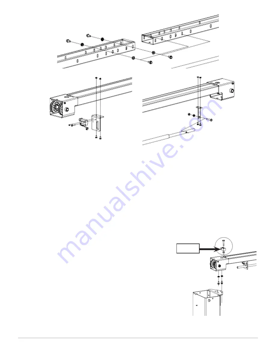
• Install the left safety bar bracket on the left overhead beam using the cross
recess head screw M6X12 and the hex nuts M6 (ref. fi g. 13). Make sure to
position the bracket adjacent the power-side column;
• Install the overhead switch on the switch bracket using the bolt M8X55 and
two nuts M8;
• Install the right safety bar bracket on the right overhead beam using the
cross recess head screw M6X12 and the hex nuts M6 (ref. fi g. 14);
• Place one end of anti-crush safety bar on
the right bracket and fi x it to the right
bracket using the bolt M8X40 and the hex
nuts M8 (ref. fi g. 14), and place another
end of anti-crush bar onto the overhead
switch through the left safety bar bracket;
• Use a lifting device to raise the assembled
beam on the mounting brackets;
• Adjust the beam to appropriate
dimensions. Tighten the fl ange bolts
M10X20 and the fl ange nuts M10 after
adjustments (ref. fi g. 15);
• Install the safety release wire guides
using the bolts M6X25 and the hex nuts
M6 (ref. fi g. 15).
Figure 12
Figure 14
Figure 13
Figure 15
Guide
Summary of Contents for APEX-10
Page 1: ......
Page 19: ...Technical Specification 19 Apex 10 Apex 10H Figure 3a Standard Version...
Page 20: ...Technical Specification 20 Apex 10 Apex 10H Figure 3b Taller Version...
Page 23: ...Technical Specification 23 Apex 10 Apex 10H Figure 6 Electrical Diagram 220V 60Hz 1PH...
Page 26: ...Safety 26 Apex 10 Apex 10H...
Page 27: ...Safety 27 Apex 10 Apex 10H...
Page 30: ...Installation 30 Apex 10 Apex 10H Figure 8a Floor Plan...
Page 61: ...Parts Catalogue 61 Apex 10 Apex 10H Parts Catalogue ED 01 2015...


