background image


REV. 01 2014


16 / 41 


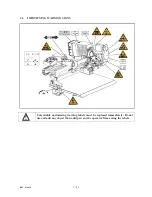
CHAPTER 6 - ORDINARY MAINTENANCE 


To ensure that this tire changer works perfectly over the years, carry out the routine maintenance 
schedule described below: 
 

1)

 Lubricate the following parts from time to time, after a thorough cleaning with naphtha: 


the various swivels on the spindle 


the tool bracket slide runner 


the carriage guide plate. 


2) 

Grease the chuck arm cylinder from time to time and also its swivel using ordinary lubricating 

grease. 
 

3)

 From time to time check the oil level in the hydraulic power pack. Use the dipstick under the 

reservoir cap. 
If necessary top up with Esso Nuto H46 or similar hydraulic oil (eg, Agip Oso 46, Shell Tellus Oil 46, 
Mobil DTE 25, Castrol Hyspin AWS 46, Chevron RPM EP Hydraulic Oil 46, BP Energol HLP). 
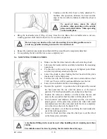
 

4)

 From time to time check the oil level in the gear unit which, when the tool carrier bracket is 

completely lowered at end travel, should not show the sight glass on the gear casing as completely 
empty. If necessary top up with Esso Spartan EP 320 or similar oil (eg, Agip F1 REP 237, BP GRX P 
320, Chevron Gear Compound 320, Mobil Gear 632, Shell Omala Oil 320, Castrol Alpha SP 320). 


If the oil in the gear unit or the hydraulic power pack has to be changed, note that 
the gear unit casing and the power pack reservoir have specific drain plug. 


Each maintenance operation must be effected only after the disconnection of the 
plug from electric network. 

Refer to the user and maintenance manuals for details on the routing 
maintenance of the generator and the compressor.  


Dispose of the used oil following the present legislation on the matter. 

Summary of Contents for TTC305

Page 1: ...REV 01 2014 1 41 ...

Page 2: ... characters are used to facilitate reading Indicates the operations which need proper care Indicates prohibition Indicates a possibility of danger for the operators BOLD TYPE Important information WARNING before operating the machine read the manual carefully for all proper operations and better functioning ...

Page 3: ...UNPACKING 8 8 4 INSTALLATION 9 4 1 INSTALLATION SPACE REQUIRED 4 2 WORKPLACEREQUIRED 4 3 FOUNDATION REQUIREMENT 4 4 ELECTRICHOOKUP 9 9 9 10 5 OPERATION 11 5 1 CONTROLS 5 2 CORRECT OPERATION CHECKS 5 3 LOCKING THE WHEEL 5 4 LIGHT ALLOY RIM LOCKING 5 5 DEMOUNTING TUBELESS TIRES 5 6 MOUNTING TUBELESS TIRES 11 12 13 14 14 15 6 ORDINARY MAINTENANCE 16 7 TROUBLE SHOOTING 17 8 MOVING STORING AND SCRAPPIN...

Page 4: ...er should be taken as correct 1 3 MANUAL KEEPING For a proper use of this manual the following is recommended Keep the manual near the lift in an easily accessible place Keep the manual in an area protected from the damp Use this manual properly without damaging it Any use of the machine made by operators who are not familiar with the instructions and procedures contained herein shall be forbidden...

Page 5: ... all responsibility for damage caused directly or indirectly by the above actions Removing or tampering with safety devices immediately invalidates the guarantee The tire changer comes complete with instruction and warning transfers which are designed to be long lasting If they should for any reason be damaged or destroyed please ask immediately for replacements from the manufacturer The machine o...

Page 6: ...8 Hydraulic power unit 9 Carriage 10 Tool holder arm 11 Frame plate 2 5 TECHNICAL SPECIFICATION Pump motor 2 HP 220V 5 209 231volts 1 phase A 30 amp breaker is required Handles rim from 13 26 Max tire diameter 55 Max tire width 30 1 2 Max wheel weight 838 LBS Gross weight 1490 Noise level in working condition 70 dB A 1 2 3 4 5 6 7 8 9 A 10 11 ...

Page 7: ...REV 01 2014 7 41 2 6 IDENTIFYING WARNING SIGNS Unreadable and missing warning labels must be replaced immediately Do not use and add any object that could prevent the operator from seeing the labels ...

Page 8: ...hown on the package itself The packaged machine may be moved by means of a fork lift truck of suitable capacity Insert the forks at the points shown in fig A 2 3 2 UNPACKING Remove the packing materials After removing the packaging from the machine make sure to check it without any damage If in doubt do not use the machine and contact your retailer A 2 660KG ...

Page 9: ...stance from walls as shown in the diagram see fig B 5 These measurements are also the tire changer working area Persons other than specially trained and authorized operators are extremely forbidden to enter this area Position the tire changer with the tool holder arm 10 fig A lowered all the way and the jaws 2 fig A closed 4 3 FOUNDATION REQUIREMENT The tire changer should be installed on a levele...

Page 10: ...ms to the voltage of the machine in compliance with the regulations in force The machine should not be started up without proper grounding It is absolutely essential that The current intake is adequately protected against over currents with fuses or automatic magneto thermic switch with rated value as shown in the table Power supply Rated current Fuse Switch 220V 230V 3ph 50 60Hz 25A AM 25A 380V 4...

Page 11: ...ic control panel to get wet Joystick 1 1 fig C Move it to position a to raise the chuck arm 3 fig A Move it to position b to lower the chuck arm Move it to position c to moves the carriage 9 fig A and the chuck arm towards each other Move it to position d moves the carriage and the chuck arm away from each other C 1 2 3 5 4 6 ...

Page 12: ... as shown by the arrows placed on the foot pedal This operation can be carried out by operaring the joystick 3 5 2 CORRECT OPERATION CHECKS Before using the tire changer make sure that it is positioned correctly on the ground Do not move your face close to the tool when you raise it When the chuck arm is lowered there is always a potential for crushing anything in its movement range Always work fr...

Page 13: ...ays a potential for crushing anything in its movement range Always work from position given in the instructions keep well out of working range of the various moving parts In locking the wheel make sure that clamps are properly positioned on the rim so as to prevent the tire from falling This operation can be extremely dangerous Do it manually only if you are certain you can keep the wheel balanced...

Page 14: ...oving the tire lubricate the beads carefully to protect them from being possible damages to facilitate the removing operations Lock the wheel on the self centering chuck as previously described and ensure that the tire is deflated Lower the tool holder arm 10 fig A into is working position Operate the joystick to move the wheel until the roller just touches the edge of the rim as shown in the figu...

Page 15: ...ool holder arm into is working position Operate the joystick 1 to position the roller against the second tire bead and turn the tire until the pliers is at the lowest position The first bead should be set on the rim at this time Position the roller at a distance of 4 5mm from the rim and press on the second tire bead in order to fit the pliers E 11 Turn clockwise and lubricate the beads and the ri...

Page 16: ...spin AWS 46 Chevron RPM EP Hydraulic Oil 46 BP Energol HLP 4 From time to time check the oil level in the gear unit which when the tool carrier bracket is completely lowered at end travel should not show the sight glass on the gear casing as completely empty If necessary top up with Esso Spartan EP 320 or similar oil eg Agip F1 REP 237 BP GRX P 320 Chevron Gear Compound 320 Mobil Gear 632 Shell Om...

Page 17: ...g correctly in its socket No power from the mains electric supply Reset the mains electric supply After having switched on the power switch the pilot lamp light on but the motor on the hydraulic power pack does not function The circuit breaker is not switched on Switch on the circuit breaker If despite of the above mentioned indications the tire changer does not work properly do not use it and cal...

Page 18: ...ing arm the slides of the carriage the tool 2 Empty oil hydraulic fluid reservoirs and wrap the machine in a sheet of protective plastic to prevent dust from reaching the internal working parts If the machine as to working again after a long storing period it is necessary to fill the oil into the reservoirs again 8 3 SCRAPPING A MACHINE When your machine s working life is over and it can no longer...

Page 19: ...ailable for the tire changer CC F100100 Set of 4 jaws for alloy rims Mounted on the jaws of the chuck they are used to operate on alloy rims without damaging them YC8 F200000 Pliers for alloy rims It is used to work with alloy rims without damaging them CC 620000 Double tools C C 6 2 0 0 0 0 ...

Page 20: ... Stop valve 3 Pump motor 12 Stop valve 4 Oil level plug 13 Carriage cylinder 5 Pressure overload valve 14 Chuck arm cylinder 6 Check valve 15 Chuck opening closing cylinder 7 2 2 solenoid valve normally open 16 Tool moving cylinder 8 Modular directional solenoid valve 17 Tool tilting cylinder 9 Modular directional solenoid valve ...

Page 21: ...2 Joystick 1 SB3 Joystick 3 foot pedal SB4 Joystick 2 SB5 Emergency stop knob YV1 Solenoid valve chuck closing YV2 Solenoid valve chuck opening YV3 Solenoid valve chuck arm lifting YV4 Solenoid valve chuck arm lowering YV5 Solenoid valve carriage moving toward chuck YV6 Solenoid valve carriage moving away from chuck YV7 Solenoid valve tool forwarding YV8 Solenoid valve tool backwarding YV9 Solenoi...

Page 22: ... DESCRIPTION QTY 1 C51B110000 Frame 1 2 C51B300000B Self centering chuck unit 1 3 C51B010000 Guide support 1 4 0205013 Washer D 12 GB T97 1 4 5 0208009 Locking washer D 12 GB T93 4 6 0201148 Screw M12X40 GB T5783 4 7 0205008 Washer D 8 GB T97 1 4 8 0201026 Screw M8X16 GB T5783 4 ...

Page 23: ...rm cylinder cover 1 25 304 JJ1300 Hydraulic hose L 1300 2 26 BZ GZ 003 Flow restrictor 1 27 C51BY30000 Chuck arm cylinder 1 28 C51B000007 Cylinder lower pin 1 29 0212004 Seeger D 25 GB T894 1 4 30 C51B000006 Cylinder upper pin 1 31 0201049 Screw M10X30 GB T5783 2 32 0205011 Washer D 10 GB T97 1 8 33 C51B000017 Chain protection support 2 34 0205022 Washer D 20 GB T97 1 3 35 C51B000010 Hose cover 1 ...

Page 24: ...hain tensioner 2 61 0213038 Split pin 2 5X25 GB T91 4 62 C51B000002 Spring guiding pin 2 63 C51B000023 Spring 2 64 0205020 Washer D 16 GB T97 1 2 65 0204008 Self locking nut M16 GB T889 1 2 66 0215093 Chain BL644X46 1 67 C51B500000 Press roller unit 1 68 C51B000009 Cylinder protection 1 69 0205004 Washer D 5 GB T97 1 2 70 0204002 Self locking nut M5 GB T889 1 2 71 C51B000022 Pipe conduit 1 72 C51B...

Page 25: ...1 5 GB T812 1 88 C51B000014 Cylinder upper pin support 1 89 C51AY42000 Carriage cylinder liner 1 90 C51BY48001 Cylinder shaft 1 91 0215020 Greaser M10X1 2 92 0206041 Screw M5X12 GB T818 2 93 0508304 Pipe clamp M18 2 94 0505033 Pedal control unit 1 95 C51B220100 Motor support extension 1 96 0201051 Screw M10X45 GB T5782 3 97 0208007 Locking washer D 10 GB T93 3 98 0203032 Nut M10 GB T6170 3 ...

Page 26: ...1 5 GB T889 2 1 3 0205022 Washer D 20 GB T97 1 1 4 CC 580102 Cross piece 1 5 CC 580103 Spacer 1 6 CC 580101 Chuck opening control plate 1 7 CC 580104 Spacer A 1 8 0205013 Washer D 12 GB T97 1 8 9 0204007 Self locking nut M12 GB T889 1 8 10 CC 510204 Spacer 4 11 CC 510205 Spacer 8 12 0205021 Washer D 18 GB T97 1 8 13 0204010 Self locking nut M18X1 5 GB T889 2 8 ...

Page 27: ...1800 1 29 0313001 Washer 1 4 4 30 0307020 Stop valve BP17000000 1 31 0303065 Union 1 4 1 32 0303010 90 union 1 4 1 33 302 WJ310 Hydraulic hose L 310 1 34 0201105 Screw M18X1 5X100 GB T5785 4 35 0202095 Screw M12X90 GB T70 1 4 36 0509026 220 380V 50 60HZ 1 5KW 4P 1 37 CC 830102V Spacer 1 38 C51B331000 Motor support 1 39 0201031 Screw GB T5783 M8X30 2 40 0209046 Screw M8X10 GB T80 1 41 YC8 3000975 B...

Page 28: ...ITEM PART NO DESCRIPTION QTY 1 C51B310000 Chuck arm 1 2 0205011 Washer D 10 GB T97 1 28 3 0201064 Screw M10X25 GB T5783 8 4 CC 201010 Carriage slider 4 5 0209024 Screw M10X25 GB T77 4 6 0204012 Nut M10 GB T6172 1 4 7 0201050 Screw M10X35 GB T5781 12 ...

Page 29: ...linder shaft 1 23 0309023 O ring 28X3 1 1 24 C 2C120 85 3 Piston 1 25 0312017 Gasket 85X65 1 26 0213029 Tab 20X60 GB T1096 2 27 C 2C120 85 1 Chuck cylinder liner 1 28 0309007 O ring 11X1 9 1 29 0305001 Plug QD07 2 30 0309026 O ring 36X3 5 3 31 0202042 Screw M8X40 GB T70 1 10 32 C 2C120 85 4 Cylinder back cover 1 33 C 2C120 85 5 Pivot union pin 1 34 0202026 Screw M6X30 GB T70 1 3 35 C 2C120 85 7 Se...

Page 30: ...51 C51B320000 Worm unit 1 52 0201068 Screw M10X40 GB T5781 2 53 CC 410101A Helical gear 1 54 0213025 Tab 8X30 GB T1096 1 55 0215024 Oil indictor M27X1 5 1 56 0201051 Screw M10X45 GB T5781 6 57 0305016 Oil plug 1 4 1 58 C51B320001 Worm support 1 59 0214019 Bearing 6205 2 60 CC 410102 Worm 1 61 0214009 Thrust bearing 51205 2 62 CC 410104 Washer 1 63 YC8 3001114 Spacer 1 64 0204014 Nut M16X1 5 2 65 C...

Page 31: ...GE UNIT ITEM PART NO DESCRIPTION QTY 1 C51B410000 Carriage 1 2 C51B400010 Rubber pad 1 3 CC 201010 Slider 4 4 0209024 Screw M10X25 GB T77 4 5 0205011 Washer D 10 GB T97 1 20 6 0201064 Screw GB T5783 M10X25 10 7 0204012 Nut M10 GB T6172 1 4 ...

Page 32: ...T97 1 1 22 CC 610001 Off center bush 1 23 C51B450000 Hook 1 24 C51B400003 Spacer 1 25 C51B440000 Cam 1 26 0201011 Screw M6X12 GB T5781 6 27 C51B400004 Washer 2 28 C51B400002 Cam limiter 1 29 C51B400011 Spring 1 30 C51B400009 Cylinder protection support 1 31 0205006 Washer D 6 GB T97 1 6 32 0202033 Screw M6X20 GB T70 1 2 33 0201050 Screw M10X35 GB T5783 12 34 C51B000015 Chain holding plate 1 35 020...

Page 33: ...0205013 Washer D 12 GB T97 1 2 58 C51BY21000 Moving cylinder liner 1 59 0204014 Nut M16X1 5 GB T6173 2 60 0312004 Gasket 45X31X15 5 2 61 C51BY28002 Piston 2 62 0309019 O ring 18X2 4 2 63 C51AY22000 Cylinder shaft 1 64 0309060 O ring 45X3 1 2 65 0305007 Guiding ring 20X10X2 5 2 66 0310006 Seal 20X28X5 7 2 67 0311022 Scraper 20X28X4 5 6 2 68 C51BY28001 Cylinder guiding cover 2 69 C51BY61000 Tilting ...

Page 34: ...ION QTY 1 C51BD12100 Support 1 2 0508277 Cable connector with 4 pins 1 3 0508350 Conduit connector M18 1 4 0511192 Cable conduit 15 8 1 5 0508282 Cable connector with 19 pins 1 6 0201136 Screw M3X10 GB T9074 4 8 7 0209042 Screw M6X8 GB T80 4 8 C51BD12001 Pivot pipe 1 ...

Page 35: ...2 Nut M4 GB52 6 13 0502044 Emergency stop knob 1 14 0505045 Manipulator 3 15 C51BD12002 Casing cover 1 16 C51BD12003 Control decal 1 17 0205004 Washer D 5 GB T97 1 4 18 0206024 Screw M5X10 GB T818 4 19 0502068 Chuck opening closing switch 1 20 0507013 Terminal board H3081 6 1 21 0507009 Terminal board H3801 12 1 22 0206018 Screw M4X30 GB T818 4 ...

Page 36: ...RIPTION QTY 1 C51AY11000 Oil tank 1 2 0305010 Oil filter 3 8 1 3 0303007 Union 3 8 1 4 BZ G18X40 Oil draining pipe 1 5 0301009 Gear pump 3 7cc 1 6 BZ BJ36 Pump joint 1 7 0309013 O ring 115X3 55 1 8 BZ ZB V6 Manifold 1 9 0307067 Non return valve 1 10 0313057 Copper washer 16X20 1 ...

Page 37: ... 1 4 24 0309019 O ring 18X2 4 2 25 0303048 Hose union 1 4 8 26 0203004 Nut M6 GB T6170 4 27 0213032 Stud M6x160 GB T901 4 28 0307098 2 2 solenoid valve normally open V389674A20 1 29 0201013 Screw M6X16 GB T5783 4 30 0202051 Screw M8X80 GB T70 1 2 31 0305025 Oil level plug 3 4 1 32 0305016 Tank plug 1 4 1 33 0305001 Sealing plug QD07 2 34 BZ W YC1 Interface block 1 35 0309014 O ring 13X1 9 2 36 O r...

Page 38: ...ITEM PART NO DESCRIPTION QTY 1 C51BD11100 Complete casing 1 2 0511026 Gasket 1 3 0211001 Seeger D 3 5 GB T896 2 4 S551 6 Pin 2 5 0505025 Power switch 20A 1 6 0508019 Plug HP 22 1 7 0205006 Washer D 6 GB T97 1 4 8 0208005 Locking washer D 6 GB T93 4 ...

Page 39: ...21 0206023 Screw M4X8 GB T818 10 22 0208002 Locking washer D 4 GB T93 9 23 0205002 Washer D 4 GB T97 1 10 24 0206016 Screw M4X20 GB T818 4 25 C61AD11302 Switch support 1 26 0206015 Screw M4X16 GB T818 1 27 0507020 Reed 6 3 4 28 CC 850223 Terminal support 2 29 0507009 Terminal board H3081 12 2 30 0206002 Screw M3X16 GB T818 4 31 0501002 Contactor 1210 AC24V 1 32 0501020 Breaker 6 3 10A 1 33 0501004...

Page 40: ...B500001 Roller shaft 1 3 C91A000002 Washer 2 4 0214038 Bearing 30212 2 5 C51B510000 Press roller 1 6 C91A000003 Thread piece M45X1 5 1 7 CC 620000 Double tool unit 1 Optional 8 CC 620001 Bead breaking disc pin 1 9 CC 620002 Bead breaking disc bush 2 10 CC 620003 Spacer 1 11 0215020 Greaser 10X1 1 12 CC 620100 Bead breaking disk 1 ...

Page 41: ...620007 Pin 2 20 CC F100100 Clamp protection kit 4 Optional 21 CC F100101 Clamp protection 4 22 YC8 F100102 Plastic insert 1 4 23 YC8 F100103 Plastic insert 2 4 24 YC8 F100104 Plastic insert 3 4 25 YC8 F100105 Bolt 4 26 YC8 F200000 Pliers for alloy rim 1 Optional 27 DB 11 00 Pliers 1 28 YC8 F201001 Plastic block 1 29 0209037 Screw M6X10 GB T80 1 30 YC8 F202001 Alloy protection 1 31 0511040 Short ti...

Reviews:

Related manuals for TTC305