2
Installation Guide
AT-HDR-M2C-QUAD
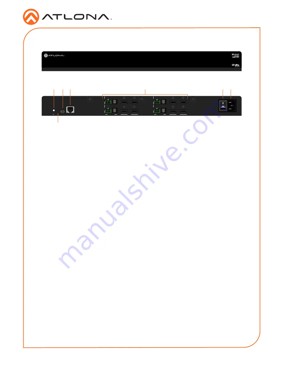
1
RESET LED Indicator
This button shows the reset status.
2
RESET Button
Press this button to reset the AT-HDR-M2C-QUAD.
3
FW
Connect a mini USB cable from a computer to this port to update the firmware.
4
LAN
Connect an Ethernet cable from this port to a Local Area Network (LAN). This port provides
access to the web GUI.
5
I/O 1 - I/O 4
The AT-HDR-M2C-QUAD provides four sets of audio and video input / output ports:
Rear
Analog Audio
Connect the included 3-pin captive
screw block from this port to a two-
channel audio output device. Refer to
Audio Connector (page 3)
for wiring
information.
Digital Audio
Connect an optical cable from this
TOSLINK connector to an AV receiver.
Only two-channel audio output is
supported.
OUT
Connect an HDMI cable from this port to
a display or other sink device. This output
supports multichannel audio.
IN
Connect an HDMI cable from this port to a
source with multichannel audio.
6
Power Button
Press this button to power-on or power-off the AT-HDR-M2C-QUAD.
7
Power receptacle
Connect the included power cable from this receptacle to an available electrical outlet.
Front
Panel Descriptions
AT-HDR-M2C-QUAD
FW
LAN
OPTICAL
L
R
AUDIO OUT
I/O 4
I/O 2
I/O 3
I/O 1
OPTICAL
L
R
AUDIO OUT
HDMI
HDMI
IN
OPTICAL
L
R
OUT
IN
OUT
IN
OUT
IN
OUT
OPTICAL
L
R
PWR: 100-240VAC 50/60Hz
RESET
AT-HDR-M2C-QUAD
1 3 4
6 7
5
2
AT-HDR-M2C-QUAD
FW
LAN
OPTICAL
L
R
AUDIO OUT
I/O 4
I/O 2
I/O 3
I/O 1
OPTICAL
L
R
AUDIO OUT
HDMI
HDMI
IN
OPTICAL
L
R
OUT
IN
OUT
IN
OUT
IN
OUT
OPTICAL
L
R
PWR: 100-240VAC 50/60Hz
RESET
AT-HDR-M2C-QUAD
AUDIO OUT
HDMI


