3
Installation Guide
AT-HDR-M2C-QUAD
1. Connect an HD/UHD source to each of the
HDMI IN
ports on the AT-HDR-M2C-QUAD.
2. Connect an HDMI cable from each
HDMI OUT
port on the AT-HDR-M2C-QUAD to a display
or other sink device.
HDMI OUT
ports support multichannel audio.
3. Connect an optical audio cable from each
OPTICAL
port on the AT-HDR-M2C-QUAD, to
a sound bar or other audio output device. Audio output on this port is limited to two-
channels.
4. Connect the included 3-pin captive screw block from each analog audio output to a set of
powered speakers or other output device. Refer to
Audio Connector (page 3)
for wiring
information.
5. Connect an Ethernet cable from the
LAN
port on the AT-HDR-M2C-QUAD, to the Local Area
Network (LAN).
6. Connect the included power cable from the power receptacle on the AT-HDR-M2C-QUAD
to an available electrical outlet.
Installation
Audio Connector
GND
+
GND
R
L
+
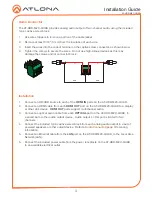
The AT-HDR-M2C-QUAD provides analog audio output of two-channel audio, using the included
3-pin captive screw block.
1. Use wire strippers to remove a portion of the cable jacket.
2. Remove at least 3/16” (5 mm) from the insulation of each wire.
3. Insert the wires into the correct terminal on the captive screw connector, as shown below.
4. Tighten the screws to secure the wires. Do not use high-torque devices as this may
damage the screws and/or connector block.


