3
Installation Guide
AT-HDVS-SC-RX
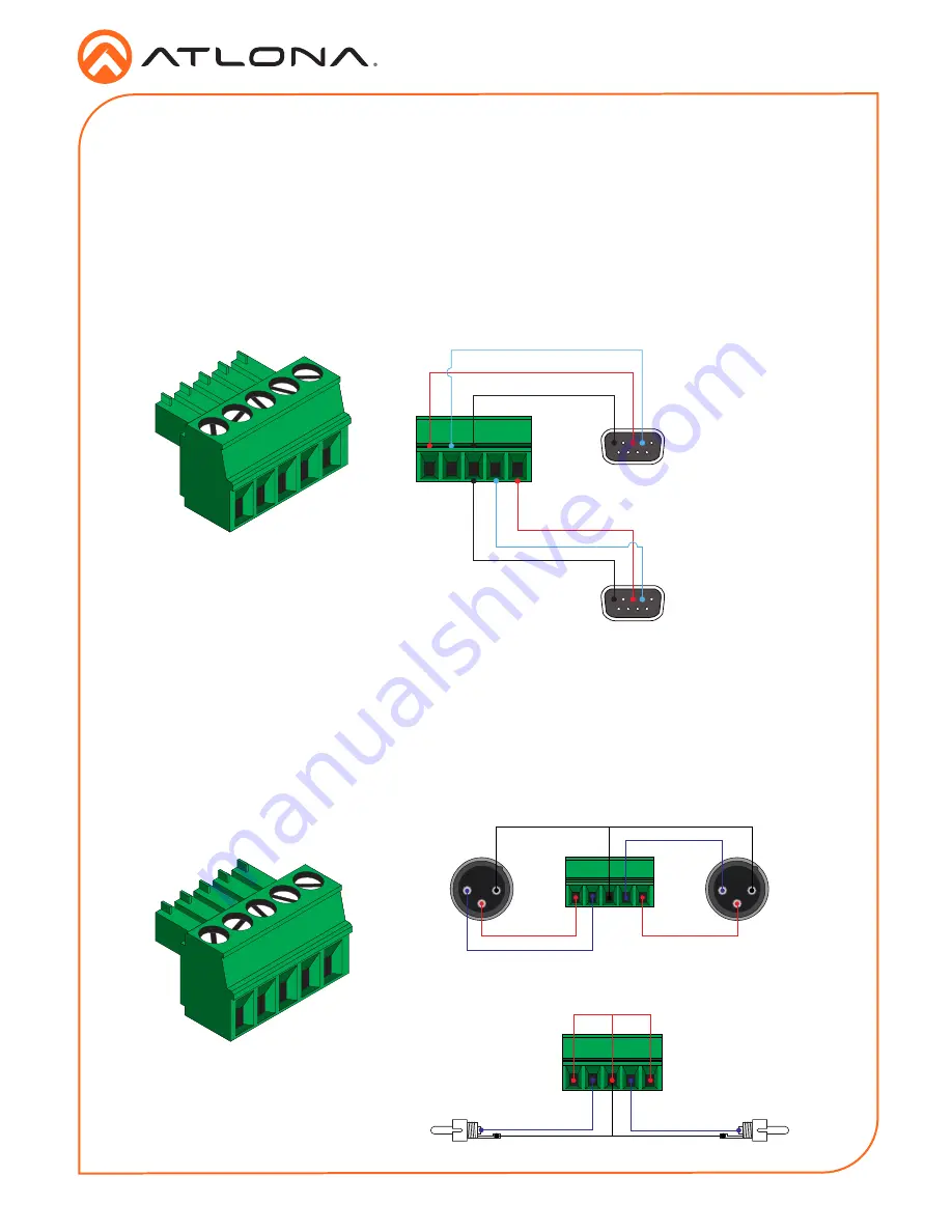
RS-232 Connector
Audio Output Connector
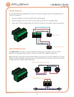
The AT-HDVS-SC-RX provides RS-232 control of both the display and/or the AT-HDVS-SC-RX.
This step is optional.
1. Use wire strippers to remove a portion of the cable jacket.
2. Remove at least 3/16” (5 mm) from the insulation of the RX, TX, and GND wires.
3. Insert the TX, RX, and GND wires into correct terminal on the included captive screw block.
The
AUDIO OUT
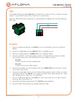
connector on the AT-HDVS-SC-RX provides the ability to connect either
balanced or unbalanced audio inputs, using the included 5-pin captive screw block.
Balanced audio connections use two signal wires and a ground to minimize interference in audio
signals. Unbalanced audio connections use one signal wire and a ground and are used if system
components don’t support balanced signals.
2
1
3
2
1
3
GND
GND
-
+
Rear View
Rear View
-
+
GND
Side View
Side View
-
+
GND
+
-
Balanced Audio using XLR Connectors
Unbalanced Audio using RCA Connectors
GND
GND
RX
TX
RX
TX
5
3 2
5
3 2
Display Control
AT-HDVS-SC-RX Control

