background image

Installation Guide

AT-VCC-IR-KIT

9

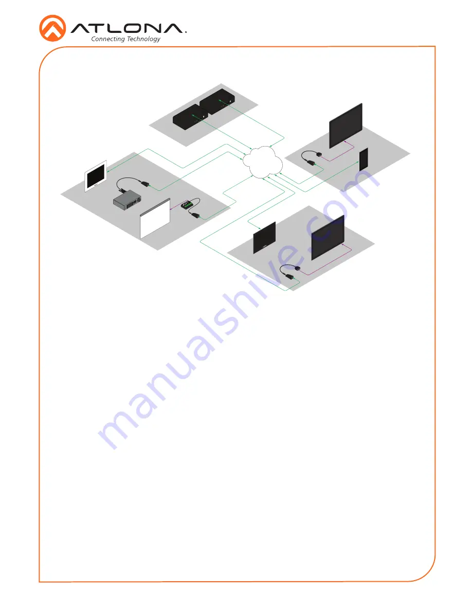
Connection Diagram

ETH

ERN

ET

HD

MI OUT

MDP O

UT

DC 1

9V

1

2

AT-VGW

-25

0

ETH

ERN

ET

HD

MI 

OUT

MDP O

UT

DC 19

V

1

2

AT-

VGW

-250

Ethernet / P

oE

Ethernet / P

oE

Ethernet / P

oE

Ethernet / P

oE

Ethernet / P

oE

Contr

ol

AT-VGW-250

AT-VGW-250

(redundancy)

Display

Ethernet

Ethernet / P

oE

Ethernet / P

oE

Ethernet

AV LAN

Room n + 1

Room 2

Room 1

IT Room

AT-VCC-IR

AT-VCC

AT-VCC-RS232

AT-VCC

Projector

AT-VTP-550-BL

AT-VTP-800-WH

Contr

ol

Display

AT-VCC-IR

AT-VCC

AT-VTP-800-BL

Contr

ol

Screen

AT-VCC-RELAY

SPST

DPDT

SPDT

Conta

ct

Closur

e

Voltage

Sen

sor

AT-VCC

Summary of Contents for AT-VCC-IR-KIT

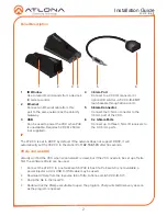
Page 1: ...dapter module includes three 3 5 mm ports for connecting the AT VCC IR EMT emitters Each port is independently addressable allowing discrete IR control of three different AV devices 1 x AT VCC 1 x AT VCC IR Package Contents Operating Notes The Velocity Command Converter must be on the same network as the Velocity Gateway AT VGW 250 or it will be unable to sync for control The AT VCC IR KIT is PoE ...

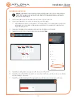
Page 2: ... 3 5mm IR receivers to the 3 3 5mm ports Panel Description IP The AT VCC is set to DHCP by default If the network does not support DHCP it will automatically set the AT VCC to the static IP of 192 168 1 70 after 30 seconds VHelp and webGUI Velocity will find the VCC when scan network is used but if the VCC needs to be set up off site first the software VHelp can be used 1 Connect the AT VCC to a n...

Page 3: ...he DHCP Enabled header this will disable DHCP and allows IP settings to be edited 8 Type in the IP details to match the network details of the Gateway e g If the Velocity gateway is located at the IP of 192 168 12 15 then the VCC should be set to an IP within the 192 168 12 XXX range that has not already been used NOTE It is best to use the webGUI to set up the static IP only as set up in Velocity...

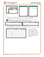
Page 4: ... 3 Open any browser on the network and type in the IP addres s of Velocity 4 Select the button from the top left corner and select Sites 5 Select the building that corresponds with the room of the VCC 6 Select the room the VCC is located in A new screen will take over the window and display the technology in the room 7 Select the button located at the top right corner of the room A new menu will o...

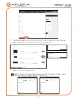
Page 5: ...evices found will appear in the unassigned list 10 Select the Add button next to the VCC A new pop up will appear 11 Select the correct mode for the VCC NOTE AT VCC IR has two modes to select from VCC IR and VCC IR Triport Select the mode based on what function device will be used ...

Page 6: ...left navigation A new screen will open 2 Create a device to be added to the room A new screen will open a Select the button at the bottom of the page to create a new device b Search for and duplicate an existing similar driver to be edited 3 Fill in the device information e g Name manufacturer etc NOTE If creating a new device the other tabs will need to be filled Follow the directions within the ...

Page 7: ... VCC IR from the Learn Device drop down menu 13 Press the NEW COMMAND button A new line will appear above the button 14 Fill in the command name of the button to be learned NOTE If a device was duplicated remove all the previous commands using the delete link ...

Page 8: ...d Syntax field Repeat the IR learn process until all needed commands are learned 19 Press the save changes button 17 When the command is successfully learned a pop up will appear with the learned IR command a Press ACCEPT to return to the commands b If there is an IR Emitter connected press TEST IR to broadcast the command to the device to verify the command works Press ACCEPT once done testing NO...

Page 9: ... e t P o E E t h e r n e t P o E C o n t r o l AT VGW 250 AT VGW 250 redundancy Display E t h e r n e t E t h e r n e t P o E E t h e r n e t P o E E t h e r n e t AV LAN R o o m n 1 R o o m 2 R o o m 1 I T R o o m AT VCC IR AT VCC AT VCC RS232 AT VCC Projector AT VTP 550 BL AT VTP 800 WH C o n t r o l Display AT VCC IR AT VCC AT VTP 800 BL C o n t r o l Screen AT VCC RELAY SPST DPDT SPDT Conta ct...

Page 10: ...Installation Guide AT VCC IR KIT 10 Notes ...

Page 11: ...Installation Guide AT VCC IR KIT 11 Notes ...

Page 12: ...f Atlona Inc All other brand names and trademarks or registered trademarks are the property of their respective owners Pricing specifications and availability subject to change without notice Actual products product images and online product images may vary from images shown here Version 2 atlona com 408 962 0515 877 536 3976 ...

Reviews: