AT-VCC-RELAY-KIT
2
Installation Guide
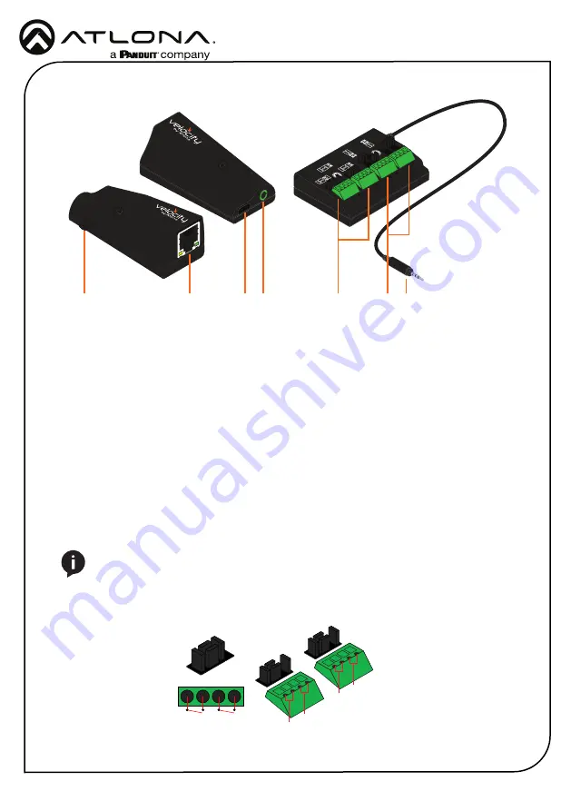
Panel Description
SPST
DPDT
SPDT
Contact
Closure
Voltage
Sensor
1
7
1
1
2
SPST
SPST
2
2
3
3
4
4
5 6
1
Ethernet
Connect an Ethernet cable from this
port to the same network as the Velocity
Gateway.
2
USB
Optional - Connect a mini USB to USB
cable here for power.
3
3.5mm Port
Connect to a VCC relay connector.
4
Relay
Connect relay here, adjusting the jumpers
to set the unit to the correct mode.
5
Sensor
Connect sensor here, adjusting the
jumpers to the correct mode.
6
3.5mm Connector
Connect the 3.5mm connector to the
3.5mm port of the VCC.
7
Factory Reset Button
Press and hold this button to reset all
settings to the factory default.
Relay
The relay has 4 terminals which vary in function depending on how the jumpers above the ports
are set.
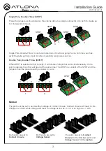
Place the jumpers as shown below, this can be done to a single connector or to both to create up
to 4 independent relays.
Single Pole, Single-Throw is best used when using a device with a simple open/close (on/off)
circuit is being used.
Single Pole, Single-Throw (SPST)
NOTE:
Relays can only work up to a maximum of 24V and 500 mA current.
C + + C


