background image

AT-VCC-RELAY

6

FCC Statement

FCC Compliance and Advisory Statement: This hardware device complies with 

Part 15 of the FCC rules. Operation is subject to the following two conditions: 1) 

this device may not cause harmful interference, and 2) this device must accept any 

interference received including interference that may cause undesired operation. This 

equipment has been tested and found to comply with the limits for a Class A digital 

device, pursuant to Part 15 of the FCC Rules. These limits are designed to provide 

reasonable protection against harmful interference in a commercial installation. 

This equipment generates, uses, and can radiate radio frequency energy and, if not 

installed or used in accordance with the instructions, may cause harmful interference 

to radio communications. However there is no guarantee that interference will not occur in a particular installation. If 

this equipment does cause harmful interference to radio or television reception, which can be determined by turning 

the equipment off and on, the user is encouraged to try to correct the interference by one or more of the following 

measures: 1) reorient or relocate the receiving antenna; 2) increase the separation between the equipment and the 

receiver; 3) connect the equipment to an outlet on a circuit different from that to which the receiver is connected; 

4) consult the dealer or an experienced radio/TV technician for help. Any changes or modifications not expressly 

approved by the party responsible for compliance could void the user’s authority to operate the equipment. Where 

shielded interface cables have been provided with the product or specified additional components or accessories 

elsewhere defined to be used with the installation of the product, they must be used in order to ensure compliance 

with FCC regulations.

1  Read, follow, and keep these instructions.
2  Heed all warnings.
3  Do not use this product near water. Keep away from 

wet places, such as: spas, pools, sinks, laundries, 

wet basements, etc.

4  When cleaning, unplug the unit and wipe with a dry 

cloth. Do not use damp cloths, cleaning fluids, or 

aerosols which may result in electric shock, fire, or 

unit damage.

5  Operate this product using only the included power 

supply and/or power cable. Use of an unapproved 

power implement may impair performance, damage 

the product, or cause fires.

6  Do not block any ventilation openings. Install in 

accordance with the manufacturer’s instructions.

7  Do not install or place this product near any heat 

sources such as radiators, heat registers, stoves, or 

other apparatus (including amplifiers) that produce 

heat.

8  Protect the power cord from being walked on 

or pinched particularly at plugs, convenience 

receptacles, and the point where they exit from the 

product.

Only use attachments/accessories specified by 

Atlona to avoid fire, shock, or other hazards.

10  To reduce the risk of electric shock and/or damage 

to this product, never handle or touch this unit or 

power cord if your hands are wet or damp. Do not 

expose this product to rain or moisture.

11  Unplug this product during lightning storms or when 

unused for long periods of time.

12  Never open, remove unit panels, or make any 

adjustments not described in this manual. 

Attempting to do so could result in electric shock, 

damage to the unit, or other hazards.

CAUTION: TO REDUCT THE RISK OF

ELECTRIC SHOCK

DO NOT OPEN ENCLOSURE OR EXPOSE

TO RAIN OR MOISTURE.

NO USER-SERVICEABLE PARTS

INSIDE REFER SERVICING TO

QUALIFIED SERVICE PERSONNEL.

CAUTION

RISK OF ELECTRIC SHOCK

DO NOT OPEN

The exclamation point within an equilateral triangle is intended to alert the user to 

the presence of important operating and maintenance instructions in the literature 

accompanying the product.

The information bubble is intended to alert the user to helpful or optional opera-

tional instructions in the literature accompanying the product.

Important Safety Information

Norway:  

This product was intended for TN power distribution system and IT power system of Norway

.

Summary of Contents for AT-VCC-RELAY

Page 1: ...AtlonaManuals CommandConverter VelocityAccessory AT VCC RELAY Command Converter IP to Relay for Velocity Control System ...

Page 2: ...AT VCC RELAY 2 Version Release Date Notes 1 11 19 Initial release Version Information ...

Page 3: ... not affect the product warranty To register your product go to http www atlona com registration Sales Marketing and Customer Support Welcome to Atlona Main Office Atlona Incorporated 70 Daggett Drive San Jose CA 95134 United States Office 1 877 536 3976 US Toll free Office 1 408 962 0515 US International Sales and Customer Service Hours Monday Friday 6 00 a m 4 30 p m PST http www atlona com Inte...

Page 4: ...oduct Warranty Terms New Products 10 years from proof of purchase date for hardware electronics products purchased on or after June 1 2013 3 years from proof of purchase date for hardware electronics products purchased before June 1 2013 Lifetime Limited Product Warranty for all cable products Limited Product Warranty Terms Refurbished B Stock Products 3 years from proof of purchase date for all R...

Page 5: ...ts or states do not allow the exclusion or limitation of relief special incidental consequential or indirect damages or the limitation of liability to specified amounts so the above limitations or exclusions may not apply to you Exclusive Remedy To the maximum extent permitted by law this limited product warranty and the remedies set forth above are exclusive and in lieu of all other warranties re...

Page 6: ... this product near water Keep away from wet places such as spas pools sinks laundries wet basements etc 4 When cleaning unplug the unit and wipe with a dry cloth Do not use damp cloths cleaning fluids or aerosols which may result in electric shock fire or unit damage 5 Operate this product using only the included power supply and or power cable Use of an unapproved power implement may impair perfo...

Page 7: ... 8 Package Contents 8 Panel Description 9 Connection Diagram 9 Configuration 10 Relay 10 Sensor 11 IP 11 VHelp and webGUI 11 Control 15 Macros 15 Event Macros 16 Room Trigger 18 Split Rooms 19 Appendix 21 Specifications 21 Table of Contents ...

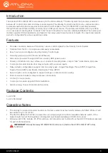
Page 8: ... over Ethernet Also can be powered through USB from a nearby USB power source Primary unit installs onto any surface via a convenient mounting dock simple click locks device into place Control port module includes four relay outputs and four sensor inputs Relay outputs configurable to support common relay types Single Pole Single Throw SPST Single Pole Double Throw SPDT and Double Pole Double Thro...

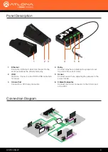
Page 9: ...mode 6 3 5mm Connector Connect the 3 5mm connector to the 3 5mm port of the VCC Connection Diagram ETHERNE T HDMI OUT MDP OUT DC 19V 1 2 AT VGW 250 ETHERNE T HDMI OUT MDP OUT DC 19V 1 2 AT VGW 250 E t h e r n e t P o E E t h e r n e t P o E E t h e r n e t P o E E t h e r n e t P o E E t h e r n e t P o E Control AT VGW 250 AT VGW 250 redundancy Display Ethernet Ethernet PoE Ethernet PoE Ethernet ...

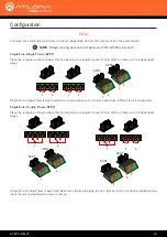
Page 10: ...mple open close off on circuit is being used Single Pole Single Throw SPST NOTE Relays can only work up to a maximum of 24V and 500 mA current 1 1 3 SPST SPST 2 2 4 3 4 Place the jumpers as shown below this can be done to a single connector or to both to create up to 3 independent relays Single Pole Double Throw SPDT 1 2 3 SPST SPDT 2 3 1 1 2 SPDT SPDT 1 2 Single Pole Double Throw is best used whe...

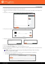
Page 11: ...tly as below to work Double Pole Double Throw DPDT 1 1 DPDT IP The AT VCC is set to DHCP by default If the network does not support DHCP it will automatically set the AT VCC to the static IP of 192 168 1 70 after 30 seconds VHelp and webGUI Velocity will find the VCC when scan network is used but if the VCC needs to be set up off site first the software VHelp can be used 1 Connect the Relay connec...

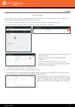
Page 12: ...edited 9 Type in the IP details to match the network details of the Gateway e g If the Velocity gateway is located at the IP of 192 168 12 15 then the VCC should be set to an IP within the 192 168 12 XXX range that has not already been used 10 Press the Save Changes button 11 Open any browser on the network and type in the IP address of Velocity 12 Select the button from the top left corner and se...

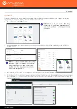
Page 13: ...elect the Add button next to the VCC A new pop up will appear 18 Select the VCC Relay Sensor from the drop down menu 19 Press the ADD VCC TO ROOM button A VCC tile will appear in the room The VCC is now ready to use Refer to the Macros Event Macros and Room Triggers section of the Velocity manual for setting up relay control Type the VCC s IP into a web browser to open the Velocity Command Convert...

Page 14: ...nsor from the drop down menu Configuration Select the Relay Sensor configurations NOTE Ensure to select the Relay type that matches how the connector was pinned Refer to Relay and Sensor sections if unsure how to set up the connector ...

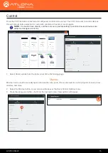
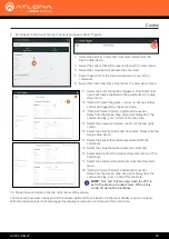
Page 15: ... up The VCC can be set to control devices through manual button selection or automatic controls with event or room triggers Macros can be used to manually open and close the relay ports this can be used to control projector screens room dividers and more NOTE It is best to have Velocity and the room set up before setting up control Ensure all devices are added and assigned correctly Macros 1 Selec...

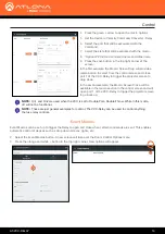
Page 16: ...Macro Screen Close will be available in the macro section in the control screen and will open port 1 of the VCC Relay to trigger the projector screen to go back up Event Macros NOTE These are just general examples for control The VCC Relay can be used to control anything that use relay controls NOTE On1 and On2 are used when the VCC is set to Double Pole Double Throw While in this mode off will no...

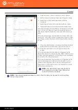
Page 17: ...Event Macro Screen Close will open port 1 of the VCC Relay to trigger the projector screen to go back up when the Room Off command within Velocity is used In the first example the Event Macro is triggered by the Room Off command and will only take effect when the room is Split This will trigger port 1 of the relay to open and break the circuit for the connected device In the second example the Eve...

Page 18: ...ociated with the command 6 Select the value that will activate the command 7 Select the Device and command that will be controlled when the sensor is triggered 8 Optional Provide a command name and Alias name 9 Press the save button in the top right corner of the screen In this example the sensor being broken will trigger Velocity to send the command Power On to the Samsung TV The VCC sensors can ...

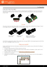
Page 19: ...this is not required for setting up the rest of the control 1 Set up the room with all the devices A big use of the Room Triggers is for Split Rooms This will provide a way to automate rooms when sensors are triggered by opening and closing of a room divider and much more Split Rooms NOTE If a device is set to All Sections when the room is split either side of the room can control that device It i...

Page 20: ...t 1 and on1 for the state 12 Select the orange and white button at the top right corner 13 Select the Velocity Command Converter Relay from the Device drop down 14 Select the sensor that will be associated with the command 15 Select the value that will activate the command 16 Select Velocity from the Device drop down menu of the command 17 Select the command Open Room from the drop down menu 18 Op...

Page 21: ...gle Pole Double Throw SPDT Double Pole Double Throw DPDT Sense Modes Voltage AC DC voltages 3 V to 24 V RMS Contact Closure Use for input from devices or feedback from external relays Power USB Micro B PoE 802 3af compliant Dimensions Inches Millimeters H x W x D AT VCC RELAY 0 90 x 3 24 x 2 00 22 86 x 82 29 x 50 80 H x W x D AT VCC 0 82 x 1 22 x 2 58 20 82 x 30 98 x 65 53 Weight Pounds Kilograms ...

Page 22: ...d names and trademarks or registered trademarks are the property of their respective owners Pricing specifications and availability subject to change without notice Actual products product images and online product images may vary from images shown here Toll free US International atlona com 877 536 3976 41 43 508 4321 ...

Reviews: