AT-VCC-RELAY
9
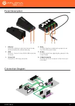
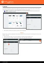
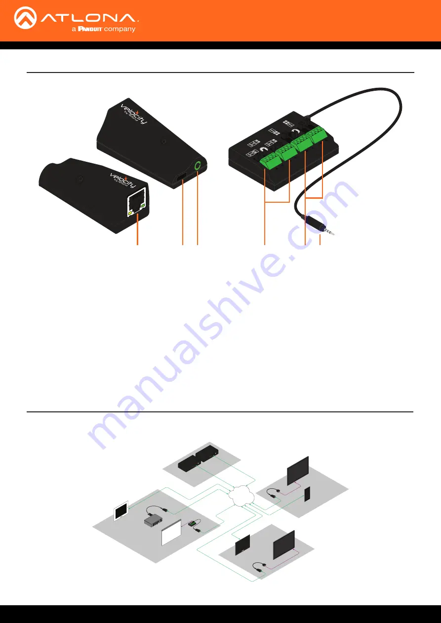
Panel Description
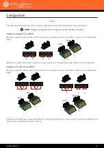
SPST
DPDT
SPDT
Contact
Closure
Voltage
Sensor
1
2 3
4
5
6
1 Ethernet
Connect an Ethernet cable from this port to the
same network as the Velocity Gateway.
2 USB
Optional - Connect a mini USB to USB cable here
for power.
3
3.5mm Port
Connect to a VCC relay connector.
4
Relay
Connect relay here, adjusting the jumpers to set
the unit to the correct mode.
5 Sensor
Connect sensor here, adjusting the jumpers to the
correct mode.
6
3.5mm Connector
Connect the 3.5mm connector to the 3.5mm port
of the VCC.
Connection Diagram
ETHER
NET
HDMI O
UT
MD
P OUT
DC 19V
1
2
AT-VGW
-250
ETHER
NET
HDMI OUT
MDP OUT
DC 19V
1
2
AT-VGW
-250
Ethernet / P
oE
Ethernet / P
oE
Ethernet / P
oE
Ethernet / P
oE
Ethernet / P
oE
Contr
ol
AT-VGW-250
AT-VGW-250
(redundancy)
Display
Ethernet
Ethernet / P
oE
Ethernet / P
oE
Ethernet
AV LAN
Room n + 1
Room 2
Room 1
IT Room
AT-VCC-IR
AT-VCC
AT-VCC-RS232
AT-VCC
Projector
AT-VTP-550-BL
AT-VTP-800-WH
Contr
ol
Display
AT-VCC-IR
AT-VCC
AT-VTP-800-BL
Contr
ol
Projector
Screen
AT-VCC-RELAY
SPS
T
DPDT
SPDT
Contact
Closure
Voltage
Sensor
AT-VCC


