2
Installation Guide
AT-OMNI-112
1
2
1
2
HDMI
PWR
LINK
VOLUME
DISPLAY
INPUT
ID
AT-OMNI-112
DC 48V
Eth 1
Eth 2
HDMI 1
HDMI 2
+
RS-232
RX TX
1
2
1
2
1
2
HDMI
PWR
LINK
VOLUME
DISPLAY
INPUT
ID
AT-OMNI-112
DC 48V
Eth 1
Eth 2
HDMI 1
HDMI 2
+
RS-232
RX TX
1
2
1
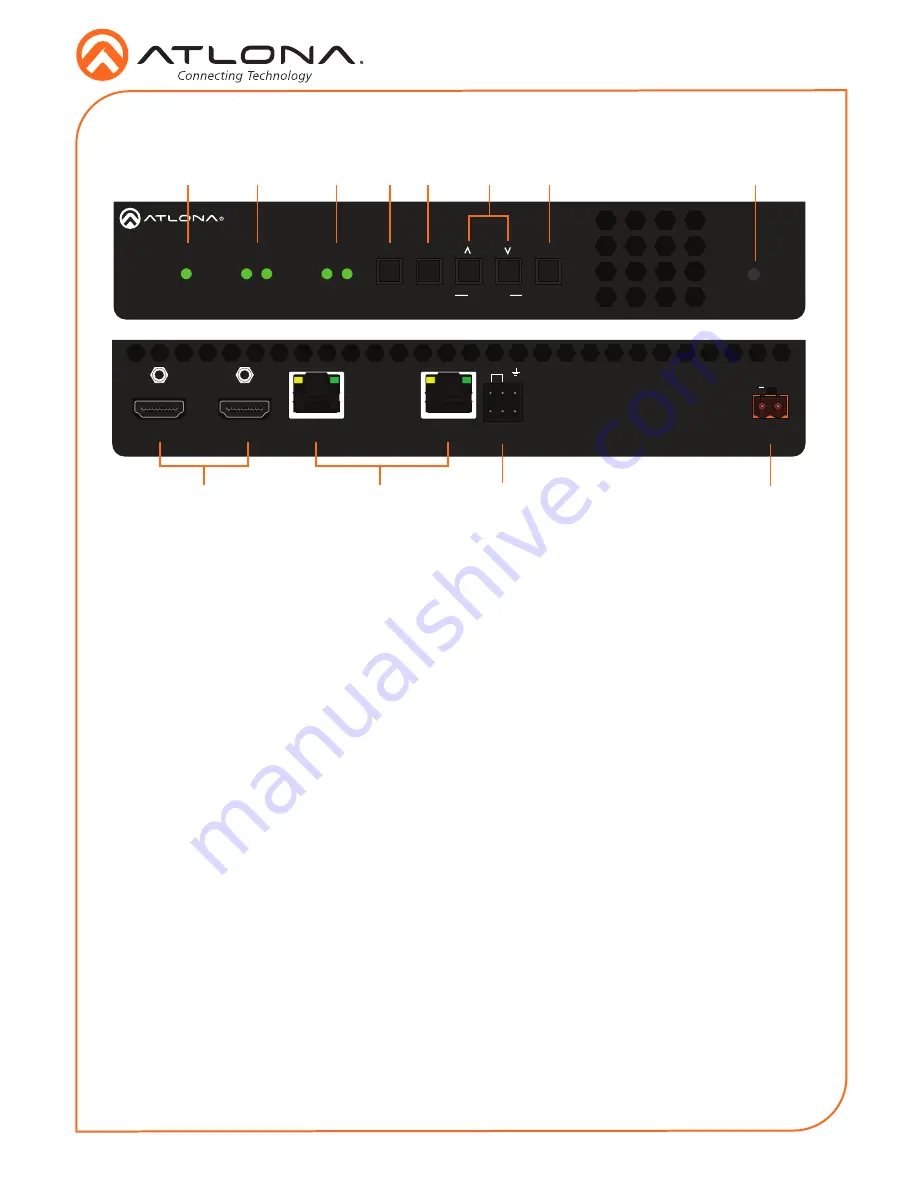
PWR
This LED indicator is green when the unit
is powered.
2
HDMI 1 / HDMI 2
These LED indicators show the active
input status.
3
LINK 1 / LINK 2
These LED indicators show the link status
of the encoder.
4
DISPLAY
Press this button to toggle the power state
of the desired display.
5
INPUT
Press this button to switch between HDMI
1 and HDMI 2 inputs.
6
VOLUME
Press these buttons to adjust the output
volume of the desired display.
7
ID
Press this button to identify the unit within
the AMS software.
8
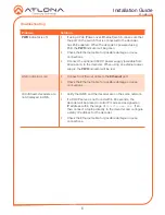
REBOOT
Use a pointed object to press this
recessed button and reboot the unit.
9
HDMI 1 / HDMI 2
Connect HDMI cables from these ports to
an HD source.
10 Eth 1 / Eth 2
Connect Ethernet cables from these ports
to the Local Area Network (LAN).
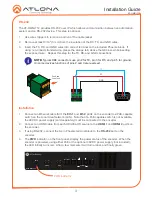
11 RS-232
Use the included Phoenix terminal block
to connect up to two RS-232 controllers
or automation systems.
12 DC 48V
Connect the optional 48V DC power
supply to this power receptacle. This
power supply is available, separately.
Panel Descriptions
1
2
3
4
5
6
7
8
11
10
9
12


