3
Installation Guide
AT-OMNI-112
The AT-OMNI-112 provides RS-232 over IP which allows communication between an automation
system and an RS-232 device. This step is optional.
1. Use wire strippers to remove a portion of the cable jacket.
2. Remove at least 3/16” (5 mm) from the insulation of the RX, TX, and GND wires.
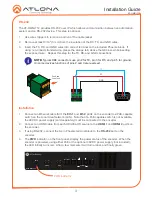
3. Insert the TX, RX, and GND wires into correct terminal on the included Phoenix block. If
using non-tinned stranded wire, presss the orange tab, above the terminal, while inserting
the exposed wire. Repeat this step for the TX, RX, and GND connections.
NOTE:
Typical DB9 connectors use pin 2 for TX, pin 3 for RX, and pin 5 for ground.
On some devices functions of pins 2 and 3 are reversed.
Push tab
to unlock
GND
RX
TX
RS-232
1
2
1
2
HDMI
PWR
LINK
VOLUME
DISPLAY
INPUT
ID
AT-OMNI-112
DC 48V
Eth 1
Eth 2
HDMI 1
HDMI 2
+
RS-232
RX TX
1
2
PWR indicator
1. Connect an Ethernet cable from the
Eth 1
and
Eth 2
ports on the encoder to a PoE-capable
switch on the Local Area Network (LAN). Note that if a PoE-capable switch is not available,
the 48V DC power supply (sold separately) must be connected to the encoder.
2. Connect an HDMI cable from each HD/Ultra HD source to the
HDMI 1
and
HDMI 2
ports on
the encoder.
3. If using RS-232, connect the 6-pin Phoenix terminal block to the
RS-232
port on the
encoder.
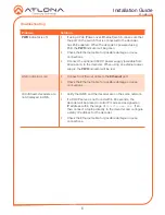
4. The
PWR
indicator, on the front panel, display the power status of the encoder. When the
encoder is powered, using either PoE or the optional 48V DC power supply (not included),
the LED initially turns red. After a few moments it will turn amber, and finally green.
Installation


