AT-OMNI-111 / AT-OMNI-112
25
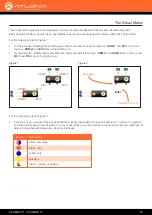
The virtual matrix provides a visual diagram of each encoder and decoder that has been detected by AMS.
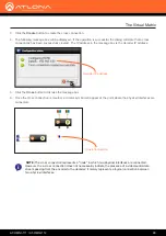
Each physical interface, source input, and display (sink) output, are arranged as follows, within the virtual matrix.
For the following, refer to
Figure 1
.
• On the
encoder
, HDMI inputs and Ethernet outputs are read from top-to-bottom:
HDMI 1
and
Eth 1
are in the
top row.
HDMI 2
and
Eth 2
are in the bottom row.
• On the
decoder
, HDMI outputs and Ethernet inputs are read left-to-right:
HDMI 1
and
HDMI 2
are in the top row.
Eth 1
and
Eth 2
are in the bottom row.
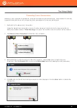
For the following, refer to
Figure 2
.
• Click the
+
icon, to expand the
physical interface
. When expanded, the icon will change to a minus (“
-
”) symbol,
and the signal types will be displayed.
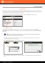
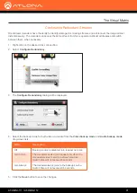
Cross connections
are color-coded to provide information on what type of
data is being passed between two
physical interfaces
.
Symbol
Description
Video and audio
Video only
Audio only
Auxiliary
Video + Audio + Auxiliary
The Virtual Matrix
Figure 1
Figure 2
HDMI 1
Eth 1
Expanded
Auxiliary Channel
HDMI 2
Eth 2
HDMI 1
HDMI 2
Eth 1
Eth 2


