background image

AT-OMNI-111 / AT-OMNI-112

56

Appendix

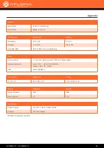
RS-232

Baud Rate

2400 to 115200 bp/s

Connector

Molex, 3-pin x 2

Temperature 

Fahrenheit

Celsius

Operating

32 to 122

0 to 50

Storage

-4 to 140

-20 to 60

Humidity (RH)

20% to 90% (non-condensing)

Power

Consumption

~13 W (w/o analog audio), TBD (w/ analog audio)

Supply (optional)

Input:  85 V ~ 264 V AC 50/60 Hz


Output:  48 V DC, 0.83 A

SKU

AT-PS-48083-C

Dimensions

Millimeters

Inches

H x W x D

34 x 208 x 112

1.34 x 8.19 x 4.41

Weight

Kilograms

Pounds

Single channel

TBD

TBD

Dual-channel

0.7

1.54

Certification

Power Supply

CE, FCC, cULus, RoHS, RCM

Product

CE, FCC, RoHS

* All VESA resolutions are 60p.

Summary of Contents for OmniStream AT-OMNI-112

Page 1: ...AtlonaManuals NetworkedAV AT OMNI 111 AT OMNI 112 ...

Page 2: ...AT OMNI 111 AT OMNI 112 2 Version Release Date Notes 1 04 17 Initial release Version Information ...

Page 3: ...stration Sales Marketing and Customer Support Welcome to Atlona Operating Notes IMPORTANT Visit http www atlona com product AT OMNI 111 and http www atlona com product AT OMNI 112 for the latest firmware updates and User Manual Main Office Atlona Incorporated 70 Daggett Drive San Jose CA 95134 United States Office 1 877 536 3976 US Toll free Office 1 408 962 0515 US International Sales and Custome...

Page 4: ...ed Product Warranty Terms New Products 10 years from proof of purchase date for hardware electronics products purchased on or after June 1 2013 3 years from proof of purchase date for hardware electronics products purchased before June 1 2013 Lifetime Limited Product Warranty for all cable products Limited Product Warranty Terms Refurbished B Stock Products 3 years from proof of purchase date for ...

Page 5: ...istricts or states do not allow the exclusion or limitation of relief special incidental consequential or indirect damages or the limitation of liability to specified amounts so the above limitations or exclusions may not apply to you Exclusive Remedy To the maximum extent permitted by law this limited product warranty and the remedies set forth above are exclusive and in lieu of all other warrant...

Page 6: ...tions 5 Do not use this product near water 6 Clean only with a dry cloth 7 Do not block any ventilation openings Install in accordance with the manufacturer s instructions 8 Do not install or place this product near any heat sources such as radiators heat registers stoves or other apparatus including amplifiers that produce heat 9 Do not defeat the safety purpose of a polarized or grounding type p...

Page 7: ...yout 24 Physical Interfaces Cross Connections 26 Creating Cross Connections 27 Removing Cross Connections 29 Scrambling 30 Configuring Redundant Streams 31 The AMS Interface 32 System Info tab 32 Input tab 34 Encoding tab 37 Serial Config tab 38 Session tab 40 Logo tab 44 Alarms tab 45 Platform 45 Video Interface 45 Audio I F 46 IP Protocol 46 Network Info tab 47 Users tab 48 License tab 49 Demo t...

Page 8: ...ependability of traditional AV distribution with the virtually unlimited scalability and cost efficiency of integrating over data networks It addresses the many challenges AV and IT integrators encounter with implementing networked AV systems while delivering immediate and long term ROI to end users in enterprises and other organizations Introduction Features Package Contents OmniStream Single Cha...

Page 9: ... the input status 3 LINK This LED indicator shows the link status of the encoder 4 REBOOT Use a small pointed object to press this recessed button and reboot the unit 5 HDMI Connect an HDMI cable from this port to an HD source 6 ETHERNET Connect an Ethernet cable from this port to the Local Area Network LAN 7 RS 232 Use the included Phoenix terminal block to connect up to two RS 232 controllers or...

Page 10: ...the desired display 5 INPUT Press this button to switch between HDMI 1 and HDMI 2 inputs 6 VOLUME Press these buttons to adjust the output volume of the desired display 7 ID Press this button to identify the unit within the AMS software 8 REBOOT Use a small pointed object to press this recessed button and reboot the unit 9 HDMI IN 1 HDMI IN 2 Connect HDMI cables from these ports to an HD source 10...

Page 11: ...32 Connection Instructions 1 Connect an Ethernet cable from the Eth port on the encoder to a PoE capable switch on the Local Area Network LAN If using the dual channel encoder connect a separate Ethernet cables to Eth 1 and Eth 2 ports 2 Connect an HDMI cable from each source to the HDMI ports on the encoder 3 RS 232 optional Connect the the RS 232 controller automation system to the RS 232 port o...

Page 12: ...X TX 1 Ethernet Ethernet Control AT OMNI 112 Control System AT OMNI 111 COM NC NO COM NC NO COM NC NO COM NC NO 12V SIG GND 12V SIG GND 12V SIG GND 12V SIG GND 1 CO MP ON EN T HD MI 1 2 3 4 5 6 SE RIA L 1 IR OU T SE RIA L 2 L R DIG ITA L CO AX OU T AU DIO OU T AU DIO IN ET HE RN ET 2 3 4 VID EO OU T 48V DC FA CTOR Y RESET Video Video V i d e o Laptop Blu Ray Player DVD Player ...

Page 13: ...r is not found within 60 seconds the encoder will be placed in Auto IP mode and assigned an IP address within the range of 169 254 xxx xxx If this occurs configure the network interface of the computer that is running AMS located on the same subnet 169 254 xxx xxx subnet mask 255 255 0 0 Refer to Configuring a Static IP Address page 15 for more information on configuring an encoder in Auto IP mode...

Page 14: ... sure that both the encoder and the computer that is running AMS are on the same subnet b Remove any network restrictions that may be in place c In AMS click Start Add Device Auto Stop mDNS Discovery This feature is enabled by default d After a few moments the following message box will be displayed Click the OK button to dismiss the message box Configuration IMPORTANT OmniStream uses mDNS as the ...

Page 15: ...C directly to one of the Ethernet ports on the encoder Make sure that the computer being used has AMS installed 3 Click Start Settings Control Panel Network and Sharing Center 4 Click Change adapter settings 5 Right click on the adapter that is used to establish a wired connection to the network and select Properties from the context menu 6 Under the Ethernet Properties dialog box select Internet ...

Page 16: ... Network info 14 Enter the required network information for the encoder in the IP Address Subnet and Gateway fields 15 Click the Save button in the bottom right corner to apply the changes 16 Disconnect the encoder from the PC and connect it to the network 17 The encoder is now ready for use ...

Page 17: ... e t OmniStream 112 Encoder Laptop DVD Player Manual Setup 1 Select the desired encoder under the Domain View pane within AMS 2 Under the Configuration Details tab click the Input tab 3 Check the Cable Present field If a cable is connected from a source to an input on the encoder then this field will be set to true If no cable is connected then this field will be set to false Note that this field ...

Page 18: ...he Encoding tab 3 Click the Input drop down list and select the input for the desired source 4 Enter the desired bit rate in the Bit Rate field Specifying lower bit rates will reduce video quality This value is in megabits per second Mbps 5 Select the bit depth from the Bit Depth drop down list Input Selection hdmi_input1 HDMI IN 1 hdmi_input2 HDMI IN 2 ...

Page 19: ...encoder only 8 Repeat steps 3 through 7 for the Encoder 2 section If a secondary HDMI source is not connected then these fields may be left at their current settings The Encoder 2 block will only be available when using a dual channel encoder AT OMNI 112 Dual channel single channel encoder 9 Click the Save button near the bottom of the page to save all changes 10 Once changes have been successfull...

Page 20: ...ncoder supports up to four sessions to enable redundancy for dual 1080p use cases The single channel encoder supports a maximum of two sessions to enable redundancy for single 1080p use cases 1 Select the desired encoder under the Domain View pane within AMS 2 Click the Session tab The Session 1 tab will be active by default 3 Under the Session 1 block select the desired interface from the Interfa...

Page 21: ...r the Encoding tab vc2_encoder1 is assigned to hdmi_input1 and vc2_encoder2 is assigned to hdmi_input2 5 Make sure that the check box next to Enabled is checked To disable video at any time click the check box to remove the check mark 6 Enter the destination multicast IP address in the Destination IP Address field By default AMS will automatically populate this field 7 Enter the port number in the...

Page 22: ...o at any time click the check box to remove the check mark 11 Enter the destination multicast IP address in the Destination IP Address field By default AMS will automatically populate this field 12 Enter the port number in the Destination UDP Port field 13 Under the AUX block select the type of control from the Source drop down list Configuration IMPORTANT AMS does not allow the same port numbers ...

Page 23: ...his field 16 Enter the port number in the Destination UDP Port field 17 Repeat steps 3 through 16 for each Session tab as required When using single channel encoders only two Session tabs will be available 18 Click the Save button near the bottom of the page to save all changes 19 Once changes have been successfully applied a message box will be displayed indicating that all changes were updated C...

Page 24: ...the icon Display sink devices are represented by the icon Physical interfaces are represented by light gray lines These lines represent the Ethernet cables which carry video audio data from an encoder to a decoder Cross connections are a logical connection between two physical interfaces and are represented by a circular symbol Click the sign next to Legend to view a list of icons and line types u...

Page 25: ...der HDMI outputs and Ethernet inputs are read left to right HDMI 1 and HDMI 2 are in the top row Eth 1 and Eth 2 are in the bottom row For the following refer to Figure 2 Click the icon to expand the physical interface When expanded the icon will change to a minus symbol and the signal types will be displayed Cross connections are color coded to provide information on what type of data is being pa...

Page 26: ...etwork a cross connection must exist between two physical interfaces Cross connections are created under the Virtual Matrix tab in AMS Figure 4a shows a cross connection that joins Ethernet 1 on the encoder to Ethernet 1 on the decoder Figure 4b shows the result of the cross connection green line in the setup Note that the second Ethernet line is still gray indicating that the cross connection for...

Page 27: ...made the cursor will turn from an arrow to a hand 2 Left click to display the Create cross Connection dialog The current sources as well as the assigned sessions will be displayed The default streaming mode is set to multicast Note that only sessions assigned to the physical interface will appear in the drop down lists To select a different video session click the Video Session drop down list and ...

Page 28: ...Click the Close button to dismiss the message box 6 Once the cross connection is created a circular symbol will appear at the point where the physical interfaces are connected Cross Connection Decoder IP address NOTE The cross connection represents a node in which two physical interfaces are connected However the a cross connection does not neccessarily indicate the presence of a video audio data ...

Page 29: ...n it will be necessary to right click on the cross connection to display the available options If Start Decoding is an option then another cross connection must be selected 2 Click Remove Cross Connection to delete the cross connection 3 AMS will display a prompt message to confirm the operation Click the OK button to delete the cross connection Click the Cancel button to return to the Virtual Mat...

Page 30: ...he virtual matrix the key is automatically generated and the Enable Scrambling box is checked A user defined key can also be created and placed in both the Key and Scrambling Key fields 1 Right click on the desired cross connection If a cross connection does not exist refer to Creating Cross Connections page 27 for more information 2 Select Enable Scrambling to being the scrambling process 3 AMS w...

Page 31: ...onnection 2 Select Configure Redundancy 3 The Configure Redundancy dialog will be displayed 4 Select the backup mode for both video and audio from the Video backup mode and Audio backup mode drop down lists 5 Click the Save button to save the changes Mode Description Off Backup source is disabled join request not sent Join Active The decoder sends a join request only when the decoder decides to sw...

Page 32: ...is optional Location Enter the text describing the location of the encoder in this field This field is optional Date Time The current date and time measured using Coordinated Universal Time UTC UTC does not observe Daylight Savings Time DST Uptime Time elapsed since the last reboot operation Temperature The current internal temperature of the unit in degrees Celsius Host Name Enter the host name i...

Page 33: ...D indicators on the front panel will flash for approximately 10 seconds WARNING The Debug button is specifically designed for providing system level troubleshooting information Do not use this feature unless directed by an experience field technician or an Atlona Technical Support Engineer Option Description Reset User Resets the encoder to factory default settings and resets custom user informati...

Page 34: ...bles may also indicate a false state EDID Selects the desired EDID EDID Description Default Default OmniStream EDID ATL 1080P 2CH 1920x1080p60 with two channel PCM audio ATL 1080P DD 1920x1080p60 with Dolby Digital audio ATL 1080P DVI 1920x1080p60 with video formatted as DVI ATL 1080P MCH 1920x1080p60 with multichannel PCM audio ATL 1280x800 RGB DVI PCWXGADVI 1280x800p60 with video formatted as DV...

Page 35: ...put audio signal is compressed such as Dolby Digital or DTS formats this field will display unknown Frequency The frequency measured in kilohertz of the input audio signal The Video Generator block contains the following information This signal can be used to test the video capability of the network Dual channel encoders will have two video generators Single channel encoders will have one video ge...

Page 36: ...gnal Framerate Enter the frame rate of the video in this field Subsampling Click the drop down list to select the chroma subsampling value of the video signal Resolution Width Enter the horizontal resolution of the video signal in this field Resolution Height Enter the vertical resolution of the video signal in this field ...

Page 37: ...econd Mbps Bit Depth Click this drop down list to select the desired maximum bit depth Any input with a higher bit depth will be reduced to the selected value Subsampling Click this drop down list to select the desired maximum chroma subsampling value Any input with a higher chroma subsampling will have their chroma scaled to the configured value using a very high quality chroma scaler to preserve...

Page 38: ...select the desired baud rate Data Click this drop down list to select the number of data bits Parity Click this drop down list to select the parity bit Stop Click this drop down list to select the stop bit Flow Click this drop down list to select the type of flow control Name The name used by AMS to identify the serial port Port Click this drop down list to select the port Mode Click this drop dow...

Page 39: ...ter the ASCII representation of the command string in this field HEX Enter the hexadecimal representation of the command string in this field Interpret on Description decoder Commands are interpreted at the decoder encoder Commands are interpreted at the encoder NOTE When entering the command string it is not required to enter the string under both the ASCII and HEX fields The encoder requires tha...

Page 40: ...k this box to enable the Session Announcement Protocol Interval Enter the SAP announcement frequency from 1 to 300 seconds in this field The default setting is 10 seconds Name Enter a name for the SAP session in the this field Description Enter a description for the SAP session in this field Originiator This field can be used to describe the origin of the feed Enabled Scrambling Check this box to ...

Page 41: ...55 seconds in this field The default value is 255 seconds DSCP Select the Differentiated Services Code Point DSCP type from the DSCP drop down list This value will be used to determine the Quality of Service QoS on a network The available values are Best Effort Low Normal High and Highest The Best Effort setting will provide normal priority for data packets while a setting of Highest will prioriti...

Page 42: ...st Effort setting will provide normal priority for data packets while a setting of Highest will prioritize data packets as critical However it should be noted that a higher priority setting may also result in high data packet loss depending upon network traffic FEC rows Specify the number of FEC rows in this field Refer to FEC Details page 51 for more information FEC Columns Specifiy the number of...

Page 43: ...he DSCP Differentiated Services Code Point type from the DSCP drop down list This value will be used to determine the Quality of Service QoS on a network RTCP Enable Click this checkbox to enable RTCP RTCP is used to monitor Quality of Service QoS and provides synchronization of data streams in multicast mode Bidirectional Click this checkbox enable bidirectional serial control This option only wo...

Page 44: ...n list Target The name used by AMS to identify the encoder Enable Click this checkbox to display the logo If this box is unchecked then the logo will not be displayed Logo Click this drop down list to select the desired logo Aspect Ratio Click this drop down list to select the type of aspect ratio to be applied to the logo Horizontal Enter the horizontal position of the logo on the screen Vertical...

Page 45: ...w Platform Video Interface Message Description Over temperature Unit temperature is exceeding operational specifications Message Description HDMI1 video absent Hot plug detected but no TMDS HDMI2 video absent Hot plug detected but no TMDS Unsupported Resolution Resolution is not supported Unsupported Frame rate Frame rate is not supported Auto switched to HDMI 1 Unit has been automatically switche...

Page 46: ...e Description HDMI1 no audio No audio signal is present HDMI2 no audio No audio signal is present No volume control unit is on mute Displayed when volume is increased while unit is in Mute mode Message Description IP address not supported Invalid IP address has been assigned ...

Page 47: ...identify the channel Enabled This field indicates that the video stream for this channel is active Carrier If this field is true then an active link exists Otherwise this field is set to false DHCP Select the desired network mode in the DHCP field Click the On radio button to enable DHCP Click the Off radio button to disable DHCP When DHCP is set to Off enter the network settings by using the IP A...

Page 48: ...lowing options from this drop down list Password Enter the password for the username Repeat Password Verify the password by retyping the password in this field Delete Deletes the user Save Saves all changes to the user Add User Click this button to create a new user User Description Administrator Ability to create delete and manage all users in addition to routing operations within the Virtual Mat...

Page 49: ...sed to install licenses on OmniStream products For OmniStream v1 0 0 all available licenses are pre installed on units at the factory License Key Enter the license number in this field Install License Click this button to install the license once the license key has been entered ...

Page 50: ...random packets on the Ethernet interface allowing the decoder to use FEC to recover the lost packets FEC should be enabled when running this test Enabling or disabling FEC can be found under the Session tab page 40 Refer to FEC Details page 51 for more information Option Description Recommendations No Errors Simulates a network with no packet drops N A Moderate Errors Simulates typical network tra...

Page 51: ...lip sync as tight as possible FEC latency overhead is also inversely proportional to bitrate the higher the bitrate the less FEC latency is introduced For applications where lip sync is very critical using a higher audio sampling rate and thus a higher audio bitrate can result in more accurate lip sync The bitrate configured on the video encoder includes FEC overhead and will automatically adjust ...

Page 52: ...arious matrix sizes It is recommended to keep lip sync within 1 frame of video to prevent any noticeable syncing issues Examples of good choices to minimize lip sync issues are Video configured for 450 Mbps FEC 10x10 Audio is 2 channel PCM 192 kHz FEC 1x4 6 40 ms 7 81 ms 1 41 ms Video configured for 900 Mbps FEC 10x10 Audio is 2 channel PCM 48 kHz FEC disabled 6 40 ms 0 ms 6 40 ms Audio additional...

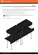
Page 53: ...ability to the rack ear use two of the included screws and attach them to the two holes directly below the enclosure screws as shown above 5 Repeat steps 1 through 4 to attach the second rack ear to the opposite side of the unit 6 Mount the unit using the oval shaped holes on each rack ear If using a drywall surface a 6 drywall screw is recommended 1 2 HDMI PWR 1 2 LINK DISPLAY INPUT ID VOLUME AT ...

Page 54: ...nt 1U rack tray The OmniStream rack tray can be purchased directly from Atlona 1 Position the OmniStream products as shown in the illustration below 2 Using the included screws secure each unit to the rack with a Philips screwdriver 3 Install the entire assembly into an empty 1U slot in the rack 1 2 1 2 HDMI PWR LINK VOLUME DISPLAY INPUT ID AT OMNI 112 1 2 LINK PW R ID AT OMNI 122 NOTE OmniStream ...

Page 55: ...t 12 bit Scaling Yes Audio HDMI LPCM 2 0 LPCM 5 1 LPCM 7 1 Dolby Digital Dolby Digital Plus Dolby TrueHD Dolby Atmos DTS 5 1 DTS HD Master Audio Analog 2 channel balanced input output Sample Rate 32 kHz 44 1 kHz 48 kHz 88 2 kHz 96 kHz 176 4 kHz 192 kHz Bit Rate 24 bit max Distance 100 meters 300 feet per hop of Gigabit Ethernet cable Signal CEC Yes display volume power input HDCP 1 4 switchable ha...

Page 56: ... 90 non condensing Power Consumption 13 W w o analog audio TBD w analog audio Supply optional Input 85 V 264 V AC 50 60 Hz Output 48 V DC 0 83 A SKU AT PS 48083 C Dimensions Millimeters Inches H x W x D 34 x 208 x 112 1 34 x 8 19 x 4 41 Weight Kilograms Pounds Single channel TBD TBD Dual channel 0 7 1 54 Certification Power Supply CE FCC cULus RoHS RCM Product CE FCC RoHS All VESA resolutions are ...

Page 57: ... registered trademarks of Atlona Inc All other brand names and trademarks or registered trademarks are the property of their respective owners Pricing specifications and availability subject to change without notice Actual products product images and online product images may vary from images shown here ...

Reviews: