AT-OMNI-121 / AT-OMNI-122
11
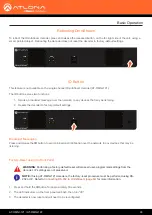
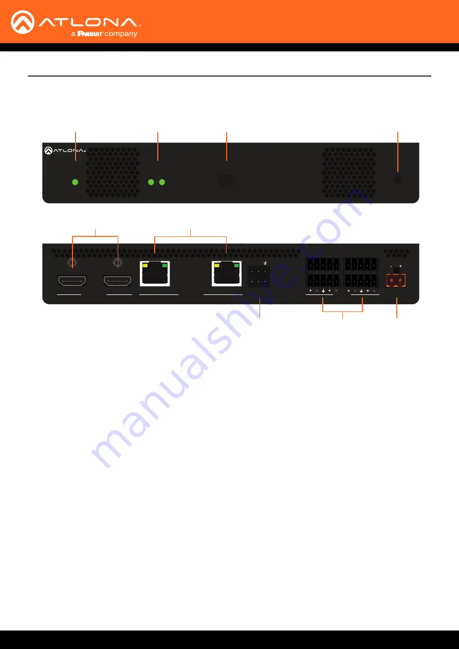
AT-OMNI-122
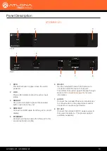
1 PWR
This LED indicator is green when the unit is
powered.
2 LINK 1 / LINK 2
These LED indicators will be green when the link
integrity between the between the encoder and
the switch is good.
3 ID
Press this button to send out a broadcast
message to any network devices that are
listening. This button is also used to set the
decoder to factory-default settings. Refer to
for more information.
4 REBOOT
Use a pointed object to press this recessed
button and reboot the unit.
5 HDMI OUT 1 / HDMI OUT 2
Connect HDMI cables from these ports to an HD
display.
6 ETHERNET 1 / ETHERNET 2
Connect Ethernet cables from these ports to the
Local Area Network (LAN).
7 RS-232
Use the included Phoenix terminal block to
connect up to two RS-232 devices to this port.
The RS-232 2 port also supports IR pass-
through. Refer to
for
more information.
8 AUDIO 1 / AUDIO 2
Connect the included Phoenix terminal blocks
to embed audio on the output stream and/or
connect to an audio output device.
9 DC 48V
Connect the optional 48V DC power supply
to this power receptacle. This power supply
is available, separately, and is required when
connecting the encoder to non-PoE compatible
switch or when embedding and de-embedding of
analog audio.
Panel Description
1
2
ID
PWR
LINK
TM
O
MNI
S
TREAM
AT-OMNI-122
ETHERNET
2
1
RS-232
AUDIO
OUT
IN
L
1
R
L
2
R
DC 48V
RX TX
1
2
2
HDMI OUT
1
1
2
ID
PWR
LINK
TM
O
MNI
S
TREAM
AT-OMNI-122
ETHERNET
2
1
RS-232
AUDIO
OUT
IN
L
1
R
L
2
R
DC 48V
RX TX
1
2
2
HDMI OUT
1
Front
Rear
1
2
3
7
9
4
5
6
8

