AT-OMNI-121 / AT-OMNI-122
54
Advanced Operation
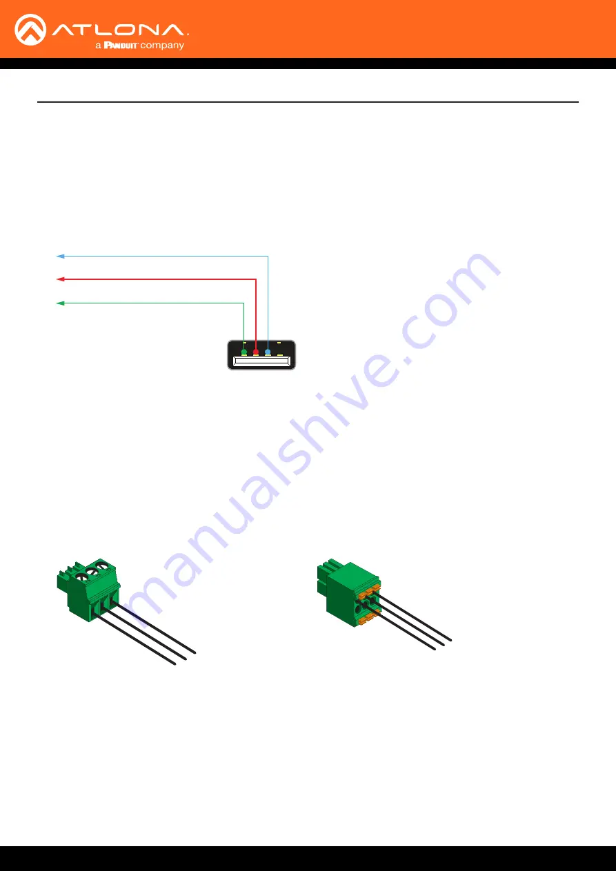
GND
TxD
RxD
GND
TxD
RxD
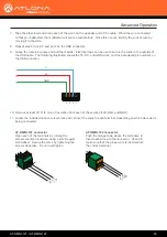
AT-OMNI-121 connector
Open each of the terminals by turning the
screws counter-clockwise, using a small regular
screwdriver. Secure the wires by tightening the
screws clockwise. Do not overtighten.
AT-OMNI-122 connector
Push the orange tabs, above the terminals, to
insert each wire into the connector. Check to
make sure that the proper wire is inserted into
the correct terminal.
7.
Take the other lead and probe each of the wires on the opposite end of the cable. When the wire connected
to that pin is detected, the multimeter will emit an audible tone. Once this occurs, identify the current wire by
moving it to the side.
8.
Repeat step 6 for pin 3 and pin 2 on the USB connector.
9.
Group the remaining wires and pull them aside. Electrical tape can be use to secure the wires to the outside of
the USB cable. The following illustration shows the TX, RX, and GND wires, and the associated pin numbers on
the USB connector.
GND
RX
TX
USB (Type-A)
4 3 2 1
10.
Remove at least 3/16” (5 mm) of insulation from each of these wires (TxD, RxD, and GND).
11.
Locate the included captive screw block and connect the wires to each terminal, depending on which decoder is
being connected.


