background image

6

Installation Guide

AT-OMNI-512

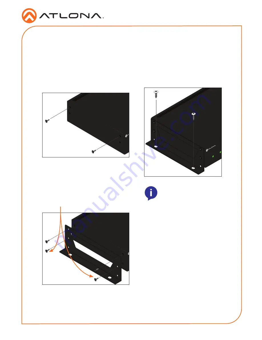
The AT-OMNI-512 encoder includes two 

mounting brackets and four mounting screws, 

which can be used to attach the unit to any flat 

surface.

1. 

Using a small Phillips screwdriver, remove 

the two screws from the left side of the 

enclosure. 


2.  Position one of the mounting brackets, as 

shown below, aligning the holes on the 

side of the enclosure with one set of holes 

on the mounting bracket.

3.  Use the enclosure screws to secure the 

mounting bracket to the enclosure. 


4. 

To provide added stability to the mounting 

bracket, use two of the included screws 

and attach them to the two holes, directly 

below the enclosure screws, as shown 

above.

5.  Repeat steps 1 through 4 to attach the 

second mounting bracket to the opposite 

side of the unit.

6. 

Mount the unit using the oval-shaped 

holes, on each mounting bracket.  If using 

a drywall surface, a #6 drywall screw is 

recommended. 


HD

MI

PW

R

LINK

TM

O

MNI

S

TREAM

ID

1

2

1

2

R

-

T

YPE

HD

MI

PW

R

LINK

TM

O

MNI

S

TREAM

ID

1

2

1

2

R

-

T

YPE

HD

MI

PW

R

LINK

TM

O

MNI

S

TREAM

ID

1

2

1

2

R

-

T

YPE

Included screws

NOTE:

 Mounting brackets can 

 also be inverted to mount the


 unit under a table or other flat 

surface.

Mounting Instructions


Summary of Contents for OmniStream AT-OMNI-512

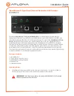
Page 1: ... HDR sources It features visually lossless compression with pristine quality video and graphics performance plus extremely low sub frame latency from encode to decode critical for demanding applications such as gaming This dual channel encoder is housed in a half width rack enclosure and is ideal for high density compact installation in a centralized equipment location IMPORTANT Visit http www atl...

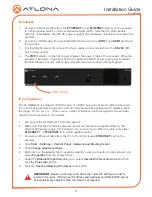
Page 2: ...oder 4 ID Press this button to identify the unit within the AMS software 5 REBOOT Use a pointed object to press this recessed button and reboot the unit 6 HDMI 1 HDMI 2 Connect HDMI cables from these ports to UHD HD sources 7 ETHERNET 1 ETHERNET 2 Connect Ethernet cables from these ports to the Local Area Network LAN 8 RS 232 IR Use the included captive screw connector to connect an automation sys...

Page 3: ...also supports either an IR extender or IR emitter This step is optional Either the top three or bottom three set of terminals can be used for RS 232 1 Use wire strippers to remove a portion of the cable jacket 2 Remove at least 3 16 5 mm from the insulation from each of the two wires 3 Insert the wires into the correct terminal on the included push spring connector following the desired wiring dia...

Page 4: ...lly be placed in Auto IP mode and will be assigned an IP address within the range 169 254 xxx xxx If this occurs a static IP address can be assigned to the encoder allowing it to be access on the network 1 Disconnect the AT OMNI 512 from the network 2 Make sure that the encoder is powered Power will need to be supplied either by the external 48V power supply not included or by connecting an Ethern...

Page 5: ... the OK button then close all Control Panel windows 12 Reconnect the AT OMNI 512 to the network Connection Diagram AT OMNI 51 2 ET HE RN ET RS 23 2 IR DC 48 V RX TX 1 2 HD MI IN 2 1 2 1 V i d e o E t h e r n e t V i d e o V i d e o C o n t r o l E t h e r n e t E t h e r n e t E t h e r n e t E t h e r n e t OmniStream 512 Encoder OmniStream 521 Decoder Projector to additional OmniStream 521 Decod...

Page 6: ...the enclosure 4 To provide added stability to the mounting bracket use two of the included screws and attach them to the two holes directly below the enclosure screws as shown above 5 Repeat steps 1 through 4 to attach the second mounting bracket to the opposite side of the unit 6 Mount the unit using the oval shaped holes on each mounting bracket If using a drywall surface a 6 drywall screw is re...

Page 7: ...cator will be green Check the Ethernet cable for possible damage or loose connections Connect the optional 48V DC power supply available from atlona com to the encoder When using an external power supply the PWR indicator will be red LINK indicator is red The optional 48V DC power supply is connected but no Ethernet cables are connected between the switch and the ETHERNET port s Check the Ethernet...

Page 8: ... Atlona Inc All other brand names and trademarks or registered trademarks are the property of their respective owners Pricing specifications and availability subject to change without notice Actual products product images and online product images may vary from images shown here Version 1 atlona com 408 962 0515 877 536 3976 ...

Reviews: