AT-OMNI-521
12
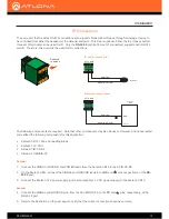
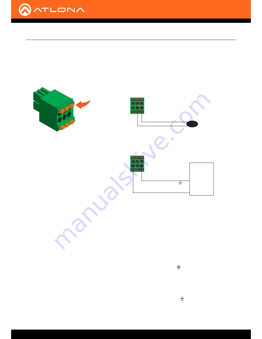
The same port that provides RS-232 connections also supports bidirectional IR pass-through, allowing a device to
be controlled from either the headend or the decoder endpoint. This step is optional. Either the top three or bottom
three set of terminals can be used for IR. Only the
RS-232 2
port (bottom set of connectors) supports both RS-232
and IR. Therefore, this port must be used for IR connections.
IR emitter configuration
IR extender configuration
Decoder
Encoder
GND (black)
IR emitter
SIGNAL (white/black)
RX TX GND
GND (black)
SIGNAL (white/black)
Control
Unit
TX out
GND
RX TX GND
IR Connections
The following components are required. Note that other components may also be used. However, Atlona has tested
and verified the following components for this application:
•
Xantech CB12 1 Zone Connecting Block
•
Xantech 12 V PSU
•
Atlona AT-IR-CS-RX
•
Atlona AT-OMNI-IR-TX
1.
Connect the SIGNAL, GROUND, and POWER leads from the Xantech CB12 to the AT-IR-SC-RX.
2.
On the Xantech CB12, connect the SIGNAL and GROUND leads to the
RX
and
pins, respectively, of the
RS-
232 2
port.
3.
Connect the Xantech 12 V power supply (or other compatible 12 V DC power supply) to the Xantech CB12.
4.
Connect the SIGNAL and GROUND pins, from the AT-OMNI-IR-TX, to the
TX
and pins, respectively, of the
RS-232 2 port.
5.
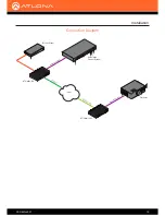
Refer to the illustration on the next page to verify that the correct connections have been made.
Push tab
to unlock
Installation

