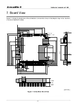
Armadillo-9
hardware manual ver.1.02
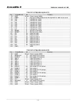
6.1.3. Structure
of
PC/104 Interrupt Controller
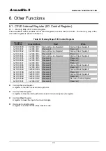
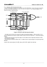
The PC/104 interrupt controller is incorporated in the CPLD (XCR3064). Types of interrupt connected to
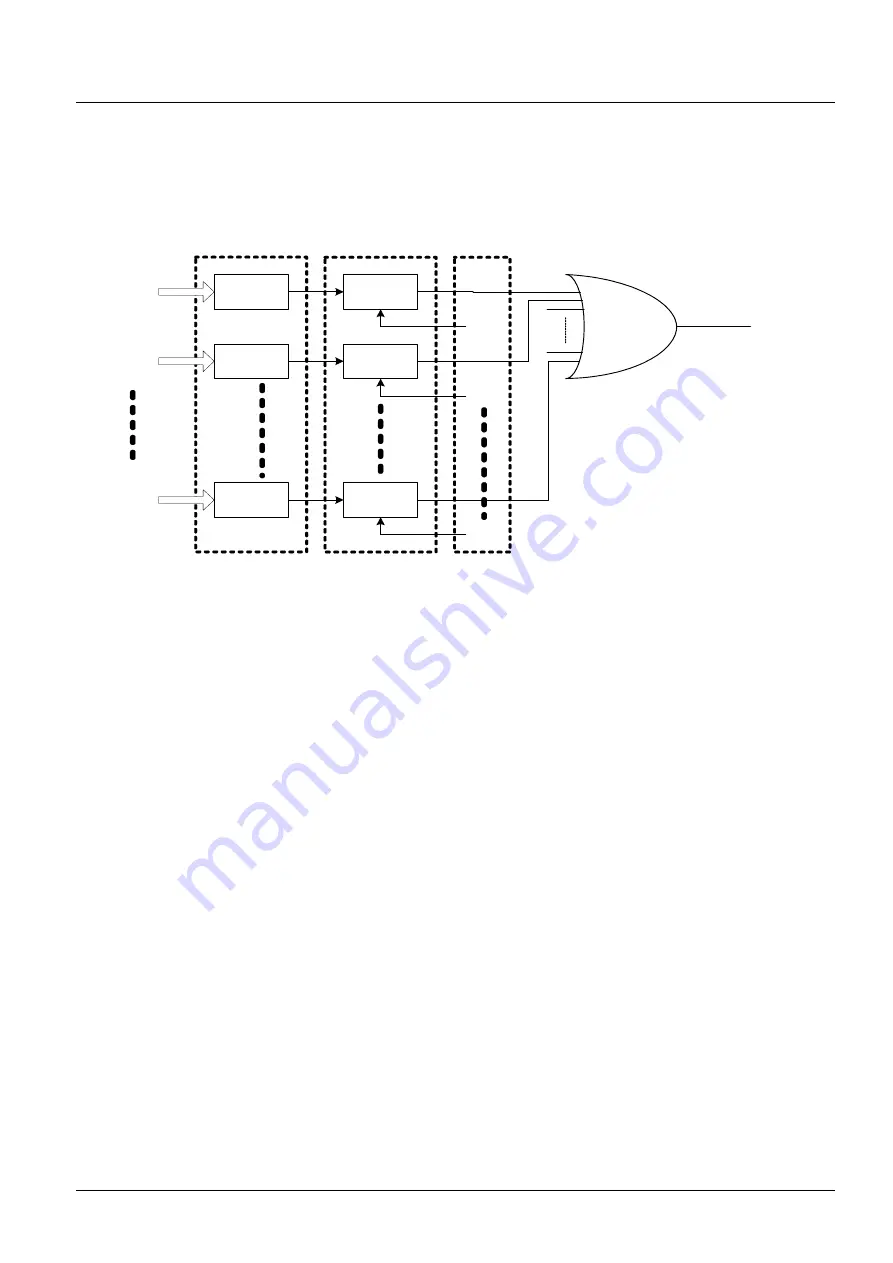
this interrupt controller include IRQ3, 4, 5, 6, 7, 9, 10,11,12, 14 and 15. The conceptual diagram of the
interrupt controller is illustrated below.
IRQ3
IRQ4
FF3
Mask3
FF4
Mask4
IRQ15
FF15
Mask15
CLR3
from CPU
CLR4
from CPU
CLR15
from CPU
Interrupt Mask Register
(Write Only)
Interrupt Service Register
(Read Only)
Interrupt Clear Register
(Write Only)
OR
ISAINT
CPU
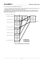
Figure 6-1 Structure of PC/104 Interrupt Controller
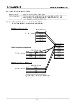
The IRQx input from PC/104 is masked by the IMR (Interrupt Mask Register). If the mask bit is ”0”, the
interrupt signal passes through the register without change, while if the mask bit is ”1”, the interrupt signal is
masked.
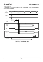
Interrupt signals that pass through the register are then retained at the FF (flip-flop) that forms the ISR
(Interrupt Service Register).
The value held in the ISR is retained until “1” is written to the bit corresponding to the ICR (Interrupt Clear
Register).
The OR of the values retained in the ISR is taken and the CPU notified of the interrupts.
28


