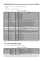
When using CON15 do not supply power from CON14 at the same time. It may
cause damage.
When using this connector to turn on the power supply, please start it with a mo-
notonically increasing supply. Also, when re-powering, make sure to first turn the
power off (5V or less for at least 10ms) and then turn it on again.
11.13. CON16 Power Output Interface
CON16 is a power output interface.
Mounted Connector
B02B-PASK(LF)(SN)/J.S.T. Mfg.
Matching Connector
Example
PAP-02V-S/J.S.T. Mfg. (Housing)
SPHD-001T-P0.5/J.S.T. Mfg. (Contact)
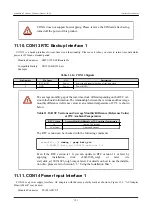
Table 11.18. CON16 Signals
Pin Number
Pin Name
I/O
Description
1
VOUT
Power
Power (VOUT)
2
GND
Power
Power (GND)
11.14. CON17 3G Antenna Interface
CON17 is an interface for the 3G module (PDS6 / Gemalto) antenna.
Mounted Connector
U.FL-R-SMT-1/HIROSE ELECTRIC
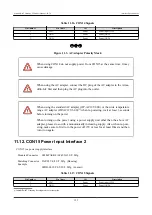
When connecting the antenna cable to the antenna terminal, please be careful not
to apply excessive force it may cause damage.
11.15. CON20 WLAN Interface
CON20 is an interface for the Wireless LAN Module (AEH-AR9462 / VoxMicro).
The PCI Express signal lines are connected to the PCI Express PHY (PCIe_PHY) on the i.MX7 Dual, and the USB signal
lines are connected via the USB HUB controller (port 3) to the USB HSIC controller of the i.MX7 Dual.
The power (WLAN_VDD) supplied to the wireless LAN module can be controlled with the ENET1_CRS (GPIO7_IO14)
pin on the i.MX7 Dual. Power is supplied with a high level output and power is turned off with a low level output.
Mounted Connector
MM60-52B1-E1-R650/Japan Aviation Electronics Industry
Armadillo-IoT Gateway G3Product Manual - INTL
Interface Specifications
123


