background image

AVR32710: Space Vector Modulation using AVR32 UC3 

Microcontroller

Features

Brushless DC Motor 

Space Vector Pulse Width Modulation using 6 PWM channels

Source Code for GCC compiler

Use AVR

®

32 Digital Signal Processing library (DSPLib)

1.

Introduction

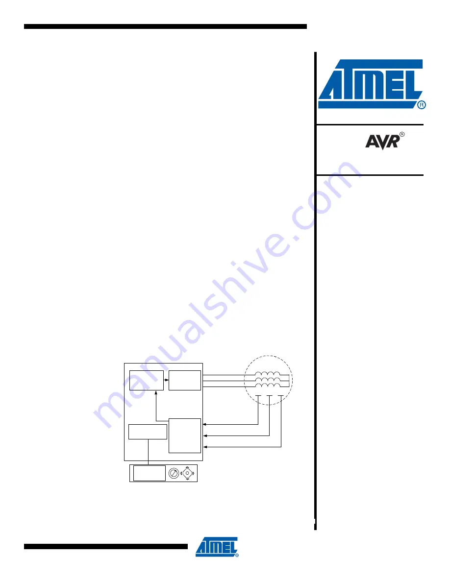
This application note outlines a demonstration using a stand-alone application on an
AVR32 target. It is a real-time system that computes Space Vector Modulation on a
Brushless DC Motor.

The Space Vector Modulation technique is described in application note 

AVR435

available on www.atmel.com.

This application is designed to work with the EVK1100 evaluation kit, therefore all the
following information is specific to this board and this specific microcontroller
(AVR32UC3A). Additionally, this application can be easily used by the EVK1101 eval-
uation kit and the specific microcontroller (AVR32UC3B).

Figure 1-1.

Block Diagram 

HallA

HallB

HallC

BLDC

Motor

Hall Sensors

U
V

W

Vn

6 PWMs

channels

3 GPIO

inputs

DSP

Library

Scheduler

LCD Display

AVR32UC3

Rev. 32094B-AVR32-05/09

32-bit 
Microcontroller

Application Note

Summary of Contents for AT32UC3 Series

Page 1: ...Motor The Space Vector Modulation technique is described in application note AVR435 available on www atmel com This application is designed to work with the EVK1100 evaluation kit therefore all the f...

Page 2: ...of AVR32 development tools for embedded systems compiler assembler linker debugger http www iar com EVK1100 The EVK1100 is an evaluation kit and development system for the AVR32 AT32UC3A microcontrol...

Page 3: ...32 05 09 AVR32710 4 Abbreviations BLDC Brushless Direct Current SVPWM Space Vector Pulse Width Modulation CW Clockwise direction CCW Counter Clockwise direction FCPU CPU frequency FPBA Peripheral Bus...

Page 4: ...o implement BLDC motor control algorithm on AVR32 UC3 devices 5 2 Space Vector Pulse Width Modulation Principle 5 2 1 Phase Switching Figure 5 1 Typical structure of the application Figure 5 1 shows t...

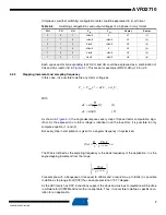
Page 5: ...ages combinations Table 5 1 Switching configurations and output voltages of a 3 phase inverter WH VH UH Van Vbn Vcn 0 0 0 0 0 0 0 0 1 Vdc 3 Vdc 3 2Vdc 3 0 1 0 Vdc 3 2Vdc 3 Vdc 3 0 1 1 2Vdc 3 Vdc 3 Vdc...

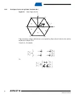
Page 6: ...rs These 3 phases voltage combinations are converted by Clarke transformation and could be expressed in complex form In sector 1 for example So 1 2 3 4 5 6 d q V1 V2 V3 V4 V5 V6 j sm s e V V 1 V dx 2...

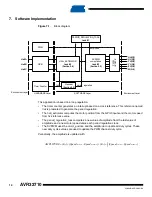
Page 7: ...n cycles sec The Ftick is defined as the sampling frequency or the basic frequency of the application n is the angle stepping increment from the range For example with a frequence of tick equal to 20K...

Page 8: ...nation at every hall sensors interrupt a new sector position is reached So that means that this interrupt should trigger a task that compute Sector Determination Algorithm electrical position of stato...

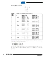
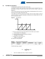
Page 9: ...use DSP library for cosinus and sinus computation Once dx and dy are calulated a set of 3 compare values Ta Tb and Tc need to be calculated every PWM period to generate this pattern Figure 6 2 PWM out...

Page 10: ...ults with SVPWM computation Sector Number q direction CCW direction CW 1 PWM0 T dx dy 2 PWM1 T dx dy 2 PWM2 T dx dy 2 PWM0 T dx dy PWM1 T dx dy PWM2 T dx dy 2 PWM0 T dx dy 2 PWM1 T dx dy 2 PWM2 T dx d...

Page 11: ...fixed value The PWM module has its own global prescaler PREA PREB bitfield in PWM MR register Each PWM channels has its own prescaler as well It is possible to define a different period for a given c...

Page 12: ...r reset and restart from 0x0000 It is possible to generate an interrupt upon RC compare match This inter rupt occurs every tick period Figure 6 4 Tick generation The Timer Counter module has its clock...

Page 13: ...tion In order to determine rotor speed we need to determine time elapsed between two interrupts The AVR32 UC3 microcontroller is able to measure time elapsed between two events using a dedicated timer...

Page 14: ...ue of amplitude and a new motor speed value each period regulation clock The SVPWM uses the motor_position and the amplitude to update all duty cycles These new duty cycles values are used to update t...

Page 15: ...or MOTOR_DRIVER BLDC_MOTOR This directory contains the service for low level drive of PWM channels SVPWM This directory contains the Space Vector computation algorithm APPLICATIONS EVK110x MOTOR CONTR...

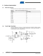
Page 16: ...entation The power bridge board is made up of standard complementary MOSFETs IRF3504 A adapta tion stage is used to convert digital signals into analog signals to correctly adress MOSFETs In this case...

Page 17: ...lug the USB cable between the PC and the EVK1100 using the USB connector Open a Cygwin or a Linux shell go to the APPLICATIONS EVK110x MOTOR CONTORL AT32UC3A0512ES GCC directory and type make rebuild...

Page 18: ...e LCD displays State of the motor Run or Stop Speed Motor value In percent of maximum value Direction Forward or Backward Push Up the Joystick The motor starts to run Push Right the Joystick The motor...

Page 19: ...ED OR STATUTORY WARRANTY RELATING TO ITS PRODUCTS INCLUDING BUT NOT LIMITED TO THE IMPLIED WARRANTY OF MERCHANTABILITY FITNESS FOR A PARTICULAR PURPOSE OR NON INFRINGEMENT IN NO EVENT SHALL ATMEL BE L...

Reviews: