170
4317I–AVR–01/08
AT90PWM2/3/2B/3B
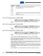
16.25.16 PSC 0 Input Capture Register – PICR0H and PICR0L
16.25.17 PSC 1 Input Capture Register – PICR1H and PICR1L
16.25.18 PSC 2 Input Capture Register – PICR2H and PICR2L
• Bit 7 – PCSTn : PSC Capture Software Trig bit (not implemented on AT90PWM2/3)
Set this bit to trigger off a capture of the PSC counter. When reading, if this bit is set it means
that the capture operation was triggered by PCSTn setting otherwise it means that the capture
operation was triggered by a PSC input.
The Input Capture is updated with the PSC counter value each time an event occurs on the
enabled PSC input pin (or optionally on the Analog Comparator output) if the capture function is
enabled (bit PCAEnx in PFRCnx register is set).
The Input Capture Register is 12-bit in size. To ensure that both the high and low bytes are read
simultaneously when the CPU accesses these registers, the access is performed using an 8-bit
temporary high byte register (TEMP). This temporary register is shared by all the other 16-bit or
12-bit registers.
Note for AT90PWM2/3 : This register is read only and a write to this register is not allowed.
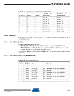
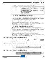
1001b
PSC Input Mode 9: Fixed Frequency Edge Retrigger PSC
1010b
Reserved (do not use)
1011b
1100b
1101b
1110b
PSC Input Mode 14: Fixed Frequency Edge Retrigger PSC and Disactivate
Output
1111b
Reserved (do not use)
PRFMnx3:0
Description
Bit
7
6
5
4
3
2
1
0
PCST0
–
–
–
PICR0[11:8]
PICR0H
PICR0[7:0]
PICR0L
Read/Write
R
R
R
R
R
R
R
R
Initial Value
0
0
0
0
0
0
0
0
Bit
7
6
5
4
3
2
1
0
PCST1
–
–
–
PICR1[11:8]
PICR1H
PICR1[7:0]
PICR1L
Read/Write
R
R
R
R
R
R
R
R
Initial Value
0
0
0
0
0
0
0
0
Bit
7
6
5
4
3
2
1
0
PCST2
–
–
–
PICR2[11:8]
PICR2H
PICR2[7:0]
PICR2L
Read/Write
R
R
R
R
R
R
R
R
Initial Value
0
0
0
0
0
0
0
0

