7
ATAB5749 [APPLICATION NOTE]
9138B–AUTO–07/15
2.
Getting Familiar with the RF Design Kit
To learn about the installation of the RF Design Kit software, refer to the application note
“ant_sd-rf-design-kit_041105_sec.pdf”. The following is a list of the first steps to take when working with the RF Design Kit
and the transmitter board:
●
Connect the RS232 cable between the microprocessor board, the ATAB-RFMB or ATAB-STK-F, to an unused PC
serial port.
●
Connect the Microprocessor board with a 12V power supply.
●
Switch on the 12V DC power supply of the microprocessor board before running the RF design Kit software.
●
The file “RF-Designkit.exe” runs the software and test the connection to the microprocessor board.
●
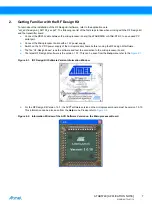
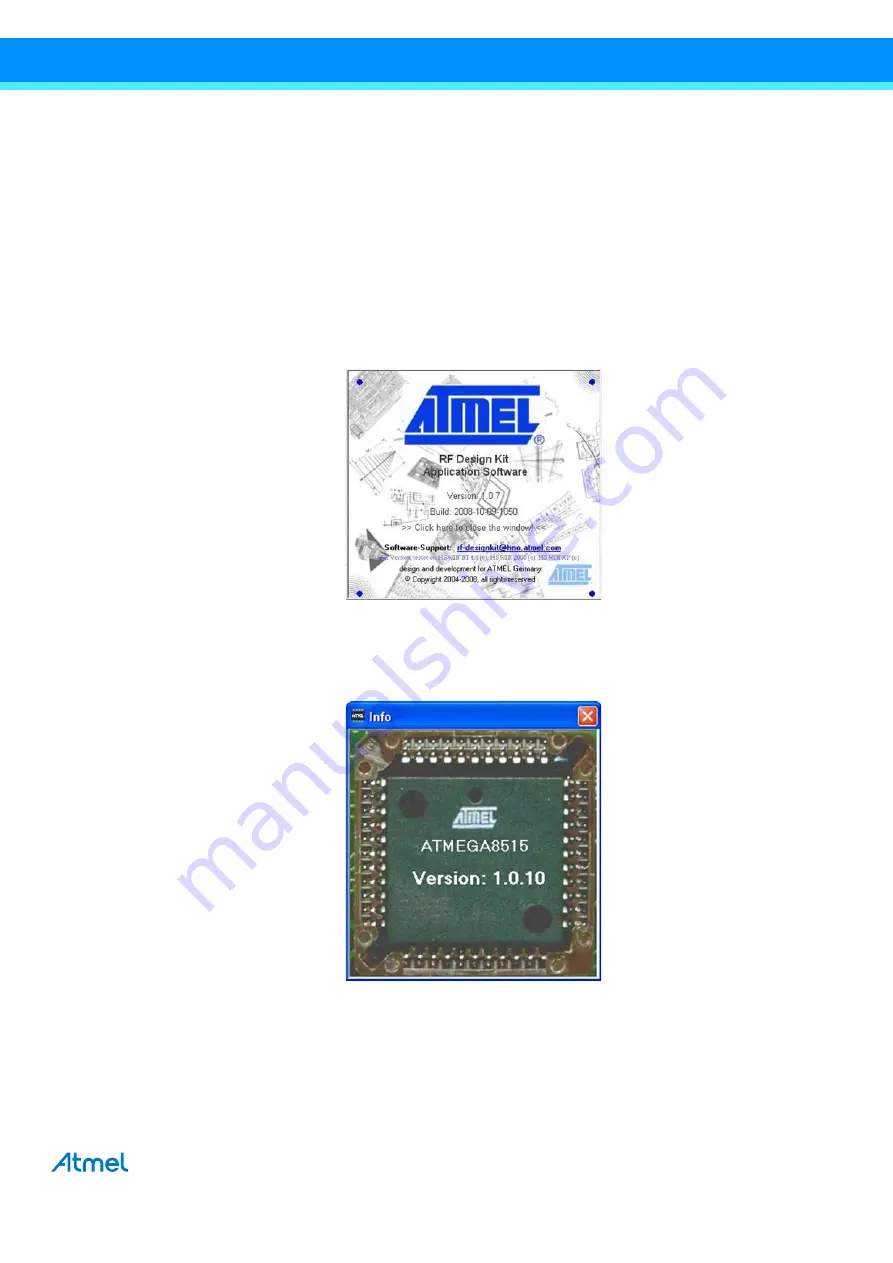
The latest RF Design Kit software is the version 1.0.7. This can be seen from the
Help
menu refer to the
Figure 2-1.
IRF Design Kit Software Version Information Window
●
For the RF Design Kit Version 1.0.7, the AVR
®
software version on the microprocessor board must be version 1.0.10.
This information can be also seen from the
Help
menu. Please refer to
Figure 2-2.
Information Window of the AVR Software Version on the Microprocessor Board

