11
ATAN0080 [APPLICATION NOTE]
9341B–AVR–02/15
5.2.2
Step-By-Step Instructions for Connecting and Operating the Kit
The following section gives step-by-step interconnection and operating instructions.
These are in reference to the interconnection instructions for the ATABtiny1634A-V1 and ATmega64M1 PCBs. System
setup and first-time operation with the GUI is also illustrated. The host GUI reports the interconnection status and depicts
LIN frame TX and RX traffic and contents between the two PCBs.
1.
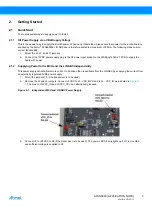
Section 2.1.1 “Kit Power Supply via a VBat Supply Voltage” on page 3
, configure the
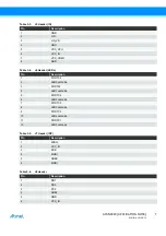
ATABtiny1634A-V1 PCB by positioning the jumpers as described here:
●
Connect the jumper at J11 to enable the voltage supply socket on X2 from the wall adapter.
●
Connect J2 (VCC_CPU) and J3 (VCC_IO) to enable VREG output voltage as the voltage source for the IO and
the Atmel ATtiny1634 CPU.
●
Connect jumpers at J9 (pins 1-2, 5-6, 9-10; use three 1x2 jumpers).
●
To use a QTouch slider: Connect the jumpers on J15 (pins 1-2, 5-6 and 9-10) to interface to the QTouch slider.
(Note: the kit is shipped in this default configuration).
●
To use QTouch buttons: Connect jumpers to J15 (pins 2-4, 6-8 and 10-12; use three 1x2 jumpers) to interface
to the QTouch buttons.
●
Connect J1 (pins 1-3, 2-4; use two 1x2 jumpers) to enable D2 and D3 when XTAL (X1) is not used.
●
Connect the J12 (AUTOBAUD) jumper to synchronize the LIN slave baud rate to the LIN master baud rate for
the first time. After successful synchronization, the synchronization timing is stored internally in the slave
EEPROM for future use.
2.
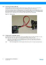
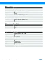
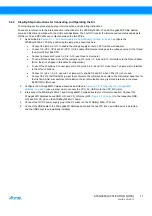
Configure the ATmega64M1 Xplained board as described in
Section 2.1.4 “Configuring the ATmega64M1
(use a jumper wire to connect the VCC_5V_USB pin to the VCC_MCU pin).
3.
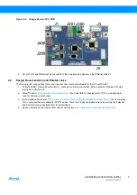
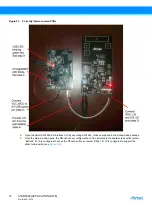
Interconnect the ATABtiny1634A-V1 and ATmega64M1 Xplained boards for LIN communication: Connect the
ATmega64M1 Xplained board GND, LIN, and VS_LIN pins (J205,
) to the respective GND,
LIN, and LIN_VS pins on the ATABtiny1634A-V1 board.
4.
Connect the 12VDC power supply plug to the X2 socket on the ATABtiny1634A-V1 board.
5.
Connect the USB cable to the ATmega64M1 Xplained board and the host PC (the new USB device is detected
and the USB driver is automatically installed).

