ATAN0080 [APPLICATION NOTE]
9341B–AVR–02/15
14
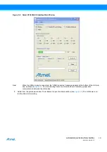
Figure 5-3.
Status Window
9.
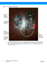
Once the GUI window is opened and the USB cable is connected, the USB LED begins to flash by oscillating
green/red and the LED0 begins to alternate ON and OFF on the PCB of the ATmega64M1 Xplained. The
green/red flashing of the USB LED indicates that the USB connection with the host GUI is correct. The LED0
flashing OFF/ON means the ATmega64M1 MCU device is executing.
Note:
LIN bus communication can only be established if the LED behavior is observed as indicated in step 9 above.
If the GUI window is not opened on the host and/or the host does not have the USB port opened, the USB LED
stays red and the LED0 is OFF and the system is not ready for operation. Reconnect the USB cable and restart
the GUI application to reset the PCB (USB LED must flash green/red and the LED0 must alternate between
ON and OFF.
10. During normal operation, the LIN frame counters should increment while the LIN error counter should stay at zero
if no transmission errors are detected.
Note:
If the “LIN Errors RX'd” parameter shows the error count incrementing and the status frame counter is NOT
incrementing in the status window, replace the AUTOBAUD jumper (J12) and cycle the power on the
ATABtiny1634A-V1 PCB to synchronize the LIN slave. Press the “Clear” button to reset the error counter in the
status window. The “LIN Errors RX'd” should stay at zero and the LIN frames counter should increment during
normal operation.
11. To test the touch sensors, push the touch buttons on the ATABtiny1634A-V1 PCB and observe the touch detection
in the main GUI window. The LEDs can also be switched ON and OFF by selecting the ON and OFF radio buttons
in the GUI window.

