Atmel AVR1923
13
8394B-AVR-02/12
Temp.
[°C]
NTC
resistance
[k
Ω
]
Temp.
[°C]
NTC
resistance
[k
Ω
]
Temp.
[°C]
NTC
resistance
[k
Ω
]
Temp.
[°C]
NTC
resistance
[k
Ω
]
-7 528.602
23 109.970
53 29.366
83 9.510
-6 499.212
24 104.852
54 28.203
84 9.185
-5 471.632
25 100.000
55 27.091
85 8.873
-4 445.772
26 95.398
56 26.028
86 8.572
-3 421.480
27 91.032
57 25.013
87 8.283
-2 398.652
28 86.889
58 24.042
88 8.006
-1 377.193
29 82.956
59 23.113
89 7.738
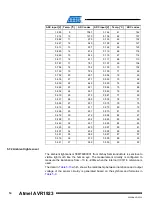
Two common approximations can be used to model the temperature vs. resistance
characteristic; these are the B parameter and the Steinhart-Hart equations.
Coefficients for both formulas can be calculated from
.
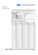
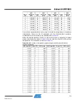
When the internal reference VCC/1.6 is used and the ADC is measuring in signed
single ended mode the codes in
can be read from the ADC at the various
temperatures. The calculation is based on
Table 5-9.
ADC codes vs. temperature (signed single ended mode with internal
VCC/1.6 reference).
ADC input [V] Temp. [°C]
ADC codes
ADC input [V] Temp. [°C]
ADC codes
2.076 -14
2047
0.347 38
345
2.030 -13
2014
0.334 39
332
1.983 -12
1968
0.321 40
319
1.936 -11
1921
0.309 41
307
1.889 -10
1875
0.297 42
295
1.841 -9
1828
0.286 43
283
1.794 -8
1781
0.275 44
273
1.747 -7
1734
0.264 45
262
1.700 -6
1687
0.254 46
252
1.653 -5
1640
0.244 47
243
1.606 -4
1594
0.235 48
233
1.560 -3
1548
0.226 49
225
1.514 -2
1503
0.218 50
216
1.469 -1
1458
0.209 51
208
1.425 0
1414
0.202 52
200
1.380 1
1370
0.194 53
193
1.337 2
1327
0.187 54
185
1.294 3
1285
0.180 55
178
1.252 4
1243
0.173 56
172
1.211 5
1202
0.167 57
165
1.171 6
1162
0.161 58
159
1.131 7
1123
0.155 59
154
1.093 8
1084
0.149 60
148

