4.1.3.
Current Measurement Header
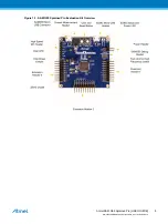
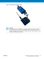
An angled 1x2, 100mil pin-header marked with MCU current measurement is located at the upper edge of
the SAM G55 Xplained Pro. All power to the ATSAMG55J19 is routed through this header. To measure
the power consumption of the device remove the jumper and replace it with an ammeter.
Caution:
Removing the jumper from the pin-header while the kit is powered may cause the
ATSAMG55J19 to be powered through its I/O pins. This may cause permanent damage to the
device.
4.2.
Peripherals
4.2.1.
Crystals
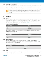
The SAM G55 Xplained Pro kit contains a 32kHz crystal mounted on it along with a footprint for a second
crystal. The crystal circuit has a cut-strap next to it which can measure the oscillator safety factor. This is
performed by cutting the strap and adding a resistor across the strap. More information about oscillator
allowance and safety factor can be found in application note
Table 4-5. External 32.768kHz Crystal
Pin on SAM G55
Function
PA07
XIN32
PA08
XOUT32
The additional crystal's pins are shared with the TWI lines in EXT3. Remove the 0Ω resistors R307 and
R306 before mounting this crystal.
Table 4-6. Footprint for Additional Crystal
Pin on SAM G55
Function
PB09
XIN
PB08
XOUT
4.2.2.
Mechanical Buttons
The SAM G55 Xplained Pro contains two mechanical buttons. One button is the RESET button
connected to the SAM G55 reset line and the other is a generic user configurable button. When a button
is pressed it will drive the I/O line to GND.
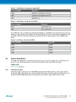
Table 4-7. Mechanical Buttons
Pin on SAM G55
Silkscreen Text
NRST
RESET
PA02
SW0
4.2.3.
LED
An yellow LED is available on the SAM G55 Xplained Pro board. The LED can be activated by driving the
connected I/O line to GND.
Atmel SAM G55 Xplained Pro [USER GUIDE]
Atmel-42389B-SAM-G55-Xplained-Pro_User Guide-04/2016
14

