Operation manual - EN
www.atmos.eu
EN - 154
ACD03/04
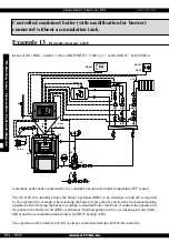
Controlled boiler (GSE) connected with accumulation tanks
Example 6
- Hydraulic diagram:
57033
5
xxxx (controlled boiler) + x
7
xxx (DKP+DHW+ACC) + xx
0
xx (-) + xxx
3
x (MK2) + xxxx
3
(MK1)
Boiler controlled by the controller based on the boiler temperature (WF sensor) and flue gas temperature
(AGF sensor).
The ACD 03/04 controller controls boiler operation (fan - FAN / PRESS + servo flap GSE - SEKGS),
the boiler circuit pump (DKP) (Laddomat/thermoregulation valve), two heating circuits (MK1, MK2),
charging and discharge of accumulation tanks and the tank (boiler) for DHW heating (SLP).
M
M
Max. 60 °C
A
AF
WF
PF
Max. 50°C
SF
ATMOS
ACD
B
2 - 6 bar
10 – 15 °C
22,5 °c
AGF
Servo SEKGS
FAN L
MK1
MK2
MKP2
MKP1
VF1
VF2
ARU30
ARU10
ARU5
DKP
SLP
10. Setting menu - Hydraulics - Hydraulic diagram
Summary of Contents for ACD 03
Page 1: ...Operation manual EN www atmos eu EN 1 ACD03 04 Operation manual ...
Page 2: ...Operation manual EN www atmos eu ACD03 04 ...
Page 8: ...Operation manual EN www atmos eu EN 8 ACD03 04 ...
Page 265: ...Operation manual EN www atmos eu EN 265 ACD03 04 12 Overview of menus and their parameters ...


