12
Setting up and starting up
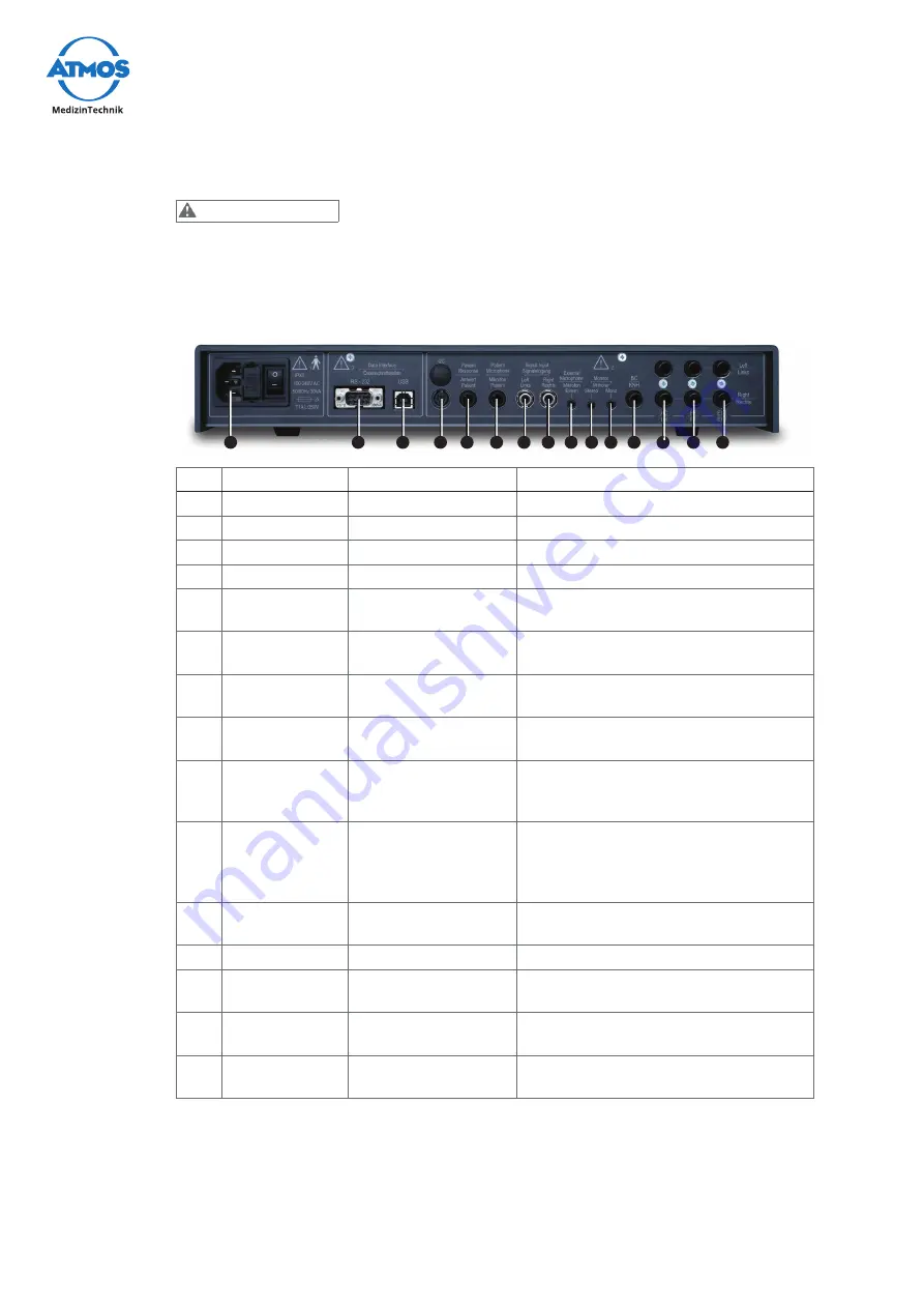
3.4 Connection diagram
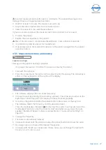
Wrong measurement results due to incorrectly calibrated transducers.
Damage to the patients hearing is possible.
•
As soon as you replace or use a diff erent transducer then the device must always be
recalibrated. In this case contact ATMOS.
13
1
2
3
4
5
6
7
8
9 10 11 12
14
15
No. Name
Connection
Note
1
Mains supply
Mains supply
2
RS - 232
Service interface
3
USB
PC
4
I2C
No function
5
Patient re-
sponse
Patient response
button
6
Microphone
patient
Patient microphone
7
Signal input left External CD player
Signal input left: white / black connec-
tor;
8
Signal input
right
External CD player
Signal input right: red connector
9
External micro-
phone
Headset (Stereo)
Red connector. The microphone in the
front panel is automatically switched
off as soon as a headset is plugged in.
10
Monitor ear-
phone stereo
Headset (Stereo)
Green connector. If the monitor
earphone (Mono) is simultaneously
plugged in, the left side of the head set
does not function.
11
Monitor ear-
phone mono
Control earphones
(Mono)
The left side of the head set is switched
off .
12
KNH
Bone vibrator
RadioEar B71
13
LH
Headphone (audiom-
eter headphone)
Sennheiser HDA280: LH left: blue
connector; LH right: red connector
14
FF
passive free fi eld
loudspeaker
Loudspeaker left: FF left.
Loudspeaker right: FF right.
15
EXT
active free fi eld
loudspeaker
Loudspeaker left: EXT left; Loudspeak-
er right: EXT right.
3.5 Use with other devices
If you connect additional devices to the audiometer, a medical system is created.
ATMOS recommends: do not use portable multiple sockets.
CAUTION


