background image


APPENDIX 

ATMOS MULTI Mk2 version 2004 

                                                                        Appendix Page 1 

Summary of Contents for Multi Mk2

Page 1: ...APPENDIX ATMOS MULTI Mk2 version 2004 Appendix Page 1 ...

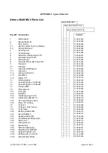
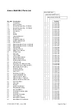
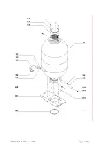
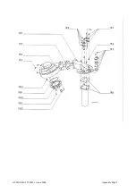
Page 2: ...ng washer 07 98 83 189 13 Connecting tube 24 Model 07 95 74 024 13 Connecting tube 32 Model 07 95 74 025 14 Fixing nut M6 07 98 82 120 15 Flow pipe set 07 95 00 003 15 1 Flow pipe 07 98 74 283 15 2 deleted 75 66 99 027 15 3 Tightening ring 22 mm 07 98 74 155 15 4 Tightening nut M27x1 5 07 98 82 119 15 5 CH Temperature sensor 07 98 63 042 15 6 Plug 1 2 O Ring 74 53 80 016 16 Tank set 07 95 05 008 1...

Page 3: ... baffle 07 98 41 016 23 Condensate collector 07 98 07 007 24 Siphon 32x140 mm 07 90 74 200 25 Sealing washer 60 mm 07 98 83 233 26 Lifting bar set 07 95 74 023 27 CH pump inc cable loom K5 07 95 36 002 28 3 Port valve inc cable loom K7 75 83 01 004 29 Return pipe for CH pump 07 98 74 284 30 Pressure sensor 07 98 78 004 31 Pump seal 30 mm 07 98 83 230 32 Union nut 1 07 98 82 113 33 Short pipe for p...

Page 4: ... 63 044 103 Appliance selection 07 98 63 045 103 Appliance selection 32 Plus Model 07 98 63 046 104 Tank temperature sensor 07 98 63 047 105 Cable loom K5 CH pump 07 98 66 208 106 Cable loom K6 07 98 66 202 Gas valve max thermostat Ionisation Ignition electrode 107 Cable loom K7 3 port valve 108 Cable loom K8 fan 07 98 66 201 109 Cable K11 main boiler earth 07 98 66 207 110 Cable loom K12 ignition...

Page 5: ...ATMOS MULTI Mk2 version 2004 Appendix Page 5 ...

Page 6: ...ATMOS MULTI Mk2 version 2004 Appendix Page 6 ...

Page 7: ...ATMOS MULTI Mk2 version 2004 Appendix Page 7 ...

Page 8: ...ATMOS MULTI Mk2 version 2004 Appendix Page 8 ...

Page 9: ...ATMOS MULTI Mk2 version 2004 Appendix Page 9 ...

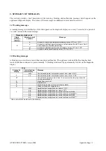
Page 10: ... be shut down requiring manually resetting before the boiler will continue operation OPERATING CODES ON ATMOS MULTI See also Table 1 in Section 5 of the Manual The following appear on the status display 1 Hot water heating operating 2 Central heating operating 3 Hot water and central heating priority to hot water 4 Hot water and central heating supply to both The dot in the bottom right hand corne...

Page 11: ...causing a malfunction The appliance waits until the blocking has been resolved and then continues to operate normally A blocking is indicated by a permanently lit letter on the diagnostic display Code Diagnostic display Central heating water display Message H H Central heating water temperature sensor error value 118 o C c L L Central heating water temperature sensor error value 10 o C C Central h...

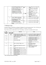
Page 12: ...l malfunction in control unit Dark display Appliance receiving no voltage 3 CAUSES OF MESSAGES 3 1 Warning messages A warning message is identified by a letter that appears on the diagnostic display every five seconds for a period of one second instead of the status message The appliance continues to operate but the function to which the message applies will be switched off of ignored Once the cau...

Page 13: ...e will start up again automatically So resetting is not necessary The possible causes are described below in order of probability Also look for the malfunction in this order Code Diagnosis Cause Diagnostic display Central heating water display c H H Central heating water temperature 118 C See cause of HH in status message b 3 1 L L Central heating water temperature 10 C See cause of LL in status m...

Page 14: ...e defective gas valve s electrical connection loose or improperly connected Air supply obstructed Flue tube obstructed Siphon obstructed Ionisation cabling not in order Ionisation probe defective or causing short circuit such as against burner No ignition ignition transformer electrical connection loose or improperly connected power cable defective ignition electrode defective or causing short cir...

Page 15: ...oose Central heating pump defective Control unit 8 High limit thermostat switches off and central heating water pressure lower than 0 5 bar Central heating water pressure incorrect Central heating water temperature sensor not properly connected to central heating water pipe Thermal safety connection defective Thermal safety defective Control unit Central heating pump not running Central heating pu...

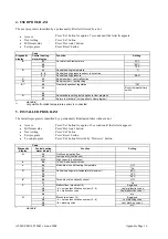
Page 16: ...GRAM The Installer program is identified by a permanently illuminated letter without a dot Access Press Set button for approx 10 seconds until the letter A appears Different value Press Hot water button Next setting Press Set button Exit program Press Reset button To sub program Press Set button followed by Hot water button Code Diagnostic display Central heating water display Function Setting A 8...

Page 17: ...ction internal on central heating water 5 C 1 0 10 C 15 15 C 2 0 20 C 5 0 0 Non standard setting only applies to service program 1 1 Return to standard only applies to service program t 1 0 Appliance recognition 24 80 1 1 Appliance recognition 24 80 plus 2 0 Appliance recognition 32 80 2 1 Appliance recognition 32 80 plus Y 7 Capacity limitation for central heating supply 24 80 and 24 80 plus 7 5 ...

Page 18: ...NCE CONTENTS OF MALFUNCTION LOGBOOK CONTENTS OF BLOCKING LOGBOOK F G 0 0 OCT 03 ANNUAL INSPECTION CONTENTS OF MALFUNCTION LOGBOOK CONTENTS OF BLOCKING LOGBOOK SERVICE ID NUMBER INCREASED BY MEANS OF HOT WATER AND SET BUTTON F G 0 0 0 07 0c 1 07 0 0 OCT 04 ANNUAL INSPECTION CONTENTS OF MALFUNCTION LOGBOOK CONTENTS OF BLOCKING LOGBOOK SERVICE ID NUMBER INCREASED BY MEANS OF HOT WATER AND SET BUTTON ...

Page 19: ...pliance Guarantee stipulations Claims can only be made on the guarantee if the enclosed GUARANTEE REGISTRATION CARD has been completed and signed and returned to Atmos within 14 days of the installation date The appliance should be installed by a recognised installer according to the Atmos Multi installation instructions and the general and local regulations applicable at the time of installation ...

Reviews: