background image

7.4 

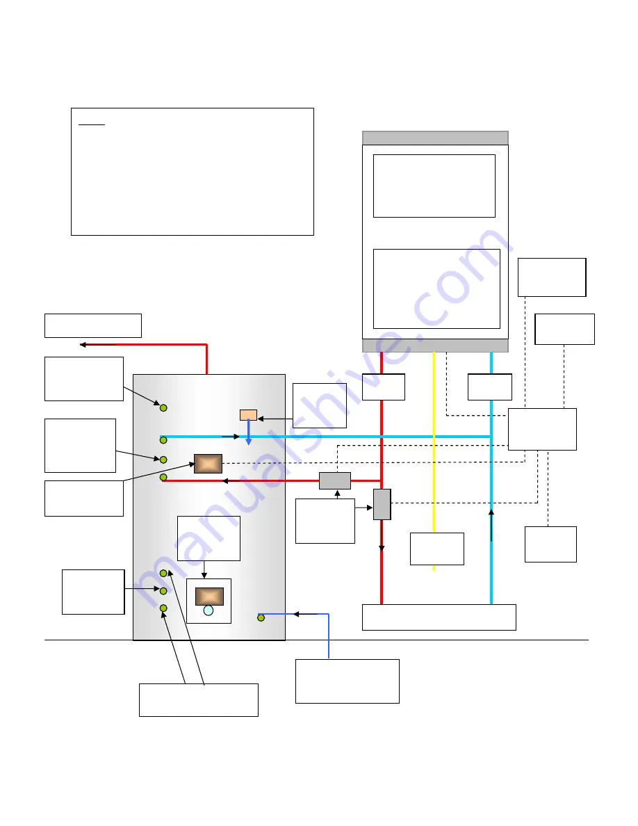
Installation Diagram for OSO Unvented Twin Coil tank with HE26 Boiler 


Room 

thermostat 

240 volt 
switched 
supply 

Electrical connection; All 
connections are 240 volt 
therefore use 240 volt 
switch live on boiler 
terminals (1 is the switched 
live input) 

Gas 
supply 

Solar coil flow and return 
connections 

Pocket for 
solar 
sensor S2  

Hot water out to taps 

Terminal box

Solar cutout 
stat & 
Immersion


heater 

Flow 

Return 

Thermostat for 
boiler control.  

Pocket for solar 
sensor S3 
(optional) 

P&T valve 
to tundish 
and 
discharge 

Commissioning 
valve and 
Secondary hot 
water return (if 
required) 

Two port 
motorised 
valves 

Time-clock 
programmer


Flow and return to radiators 

Cold inlet with valve 
assembly as supplied 
with tank 

Atmos 
InterSystem HE26 
condensing gas 
boiler 

Note 
Tank is OSO unvented tank with internal 
secondary expansion 

Note: This is a diagrammatic illustration 
only, and does not override manufacturer’s 
instructions for boiler and unvented hot 
water tank. 
Solar circuit shown on page 9. 

Twin Coil Sealed Solar System Ins Man  


                           Page 14 of 15 

Summary of Contents for Twin Coil Sealed Solar System

Page 1: ...allation User Manual THIS MANUAL IS TO BE LEFT WITH THE HOUSEHOLDER AFTER INSTALLATION Atmos Heating Systems West March Daventry Northants NN11 4SA Tel 01327 871990 Fax 01327 871905 e mail sales atmos uk com internet www atmos uk com T2 panels enlarged Appendix Issue 3 12 07 ...

Page 2: ...Twin Coil Sealed Solar System Ins Man Page 2 of 15 ...

Page 3: ... in the centre of the roof 1 2 2 The minimum angle of the roof and therefore the solar panel should be 30 degrees The maximum height of the solar panel should normally be 10 metres 1 2 3 Ensure that there will be enough space to fit the solar panel Because of the flashing in the case of roof integrated panels it is best to have at least one column of tiles between the panel and a vertical edge and...

Page 4: ...stalling Roof Integrated Solar Panels For pantiles etc but not slates See separate leaflet available from Atmos 3 0 Installing On Roof Solar Panels 2 Panels Twin Coil Sealed Solar System Ins Man Page 4 of 15 ...

Page 5: ...3 Panels Twin Coil Sealed Solar System Ins Man Page 5 of 15 ...

Page 6: ... secure the solar panels to the U profile Be careful not to strip the thread 10 Check the seating of the parts and the tightness of all the pipe joints Quantity Description 2 pan 3 pan 2 2 2000mm Supporting profile 2 1500mm Supporting profile 6 8 Bearing hook 6 8 Fastener 1 1 2215mm G profile 1 1115mm G profile 1 1 2215mm U profile 1 1115mm U profile 12 16 8 x 50mm screw 12 16 6 x 20mm screw 4 6 5...

Page 7: ... than the given channel DTO The solar pump is switched off when the difference in temperature between S1 and S2 is smaller than the given channel DTF If the temperature rises above the maximum storage temperature channel SMX the solar pump switches off If a temperature of above 140 C factory setting but adjustable channel EM at the controller is reached at the solar panel sensor the solar pump is ...

Page 8: ...n Mineral wool 66 mm thick Side insulation Mineral wool 20 mm thick Connection G3 flat packing Absorber All copper absorber with highly selective surface Absorption 95 2 Emissivity 5 Working pressure 2 4 Bar Content 1 1 Litre Efficiency Certification by an independent testing laboratory ISE Freiburg EN 12975 1 2 Maximum efficiency η0 0 77 77 Stagnation temperature no load operation 202 C Other inf...

Page 9: ...nk 240 volt switched supply Atmos Heating Systems Installation diagram for Twin coil tank with Single station pump set BS 3 controller KEY 1 Integrated compensator within panel has stainless steel pipe with male connection flexi connector 2 inch brass end cap with washers 3 22mm inch MI compression elbow with washers 4 a Connect inch brass nipple in one end of inch brass tee b Connect x inch brass...

Page 10: ...hermostat and remove the control thermostat part so that just the 85 deg C limit thermostat is left Fit the tank sensor using heat conductive paste and the limit thermostat into the lower pocket double segment and bring the sensor cable out through the thermostat spare gland 3 Keep sensor cables separate apart from other cables 4 An additional sensor S3 can be fitted into the pocket near the top o...

Page 11: ...s shown in the Appendix 10 Equipotential bonding is refitted 11 Pump speed set to the highest 12 Solar panel system has been filled with anti freeze anti corrosion fluid 13 De aeration valves manually bled 14 Solar panel system pressurised at 3 to 4 bar 15 Solar system controller operation checked and the controller left in AUTO 16 The pump unit is fixed securely and not vibrating or noisy Pump op...

Page 12: ...Hot water out to taps Terminal box Immersion heater Unvented tank expansion vessel white as supplied with tank Connect to cold water inlet assembly with braided hose Flow and return to radiators Flow Return Room thermostat Thermostat for boiler control Pocket for solar sensor S3 optional Gas supply Secondary hot water return blank off if not required Electrical connection All connections are 240 v...

Page 13: ...7 3 Controls Diagram for RCM Unvented Twin Coil tank with HE26 Boiler Note Diagram shows Salus controls Twin Coil Sealed Solar System Ins Man Page 13 of 15 ...

Page 14: ...ostat for boiler control Pocket for solar sensor S3 optional P T valve to tundish and discharge Commissioning valve and Secondary hot water return if required Two port motorised valves Time clock programmer Flow and return to radiators Cold inlet with valve assembly as supplied with tank Atmos InterSystem HE26 condensing gas boiler Note Tank is OSO unvented tank with internal secondary expansion N...

Page 15: ...7 5 Controls Diagram for OSO Unvented Twin Coil tank with HE26 Boiler Note Diagram shows Salus controls Twin Coil Sealed Solar System Ins Man Page 15 of 15 ...

Reviews: