background image

4

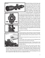
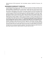
Remove the tops of both rings and 
inserts and cradle the scope in their 
lower halves. Install the top halves 
and tighten each ring’s four screws 
to finger tight (Figure 1). Do not over 
tighten or you will be unable to rotate 
the offset inserts.  The use of a bore 
sight or collimator at this stage is very 
helpful setting the initial alignment 
of scope and bore.  This can also be 

accomplished by placing a well-lit and defined bull’s-
eye target with at least a 6-inch black, 100 yards from 
a sand bagged and well supported rifle.  Using the 100-
yard distance to target will give a convenient zero but 
other distances can be used.  It will, however, require 
more adjustment during live fire to achieve a 100 yd. 
zero.  Sighting thru the bore with the action open center 
the black bull’s-eye in your rifles bore.  You would like 
the black circle of the bull’s-eye centered in the scopes 
field of view with the crosshair in the center of the bull.   

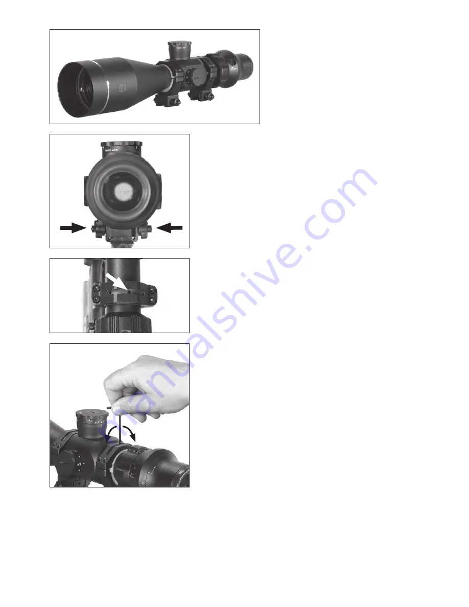
If it is not, first use the side nuts that secure the rings to 
the bases to adjust the scope to zero windage (Figure 
2).  Alternately loosening and tightening the side nuts 
while checking the bores alignment will move the scope 
crosshair accordingly:
Looking from behind the scope in normal shooting posi-
tion.
Loosening the rear rings left side nut and then retight-
ening the right side will move the crosshair to the left.  
Reversing this procedure will move the crosshair to the 
right.
Adjustment using the front rings screws will result in the 
opposite.
Loosening the front rings left side nut and tightening the 
right will move the crosshair to the right.
Next check the elevation for zero.  If the crosshair is not 
centered adjust it by rotating the a centric inserts via the 
following method:
Use the slot milled into the top half of each ring to 
access the holes drilled thru the insert (Figure 3).  Move 

the inserts radially to achieve the above described scope picture by inserting a round rod 
into the holes drilled in the insert (Figure 4).  The shank (blunt end) of a 9/64 drill works 
perfectly.  When the reticle is centered, tighten the ring screws exerting torque on the 
short end of the supplied allen wrench.  It is not necessary to use the leverage of the long 
arm to tighten the screws any more than an additional 1/8 turn.

Figure 2

Figure 1

Figure 4

Figure 3

Summary of Contents for 2-6x68 DNS

Page 1: ...partment of Commerce It is unlawful and strictly prohibited to export or attempt to export or otherwise transfer or sell any hardware or technical data or furnish any service to any foreign person whe...

Page 2: ...t Cap 450 mw IR Illuminator Night Vision Eyepiece Eyepiece Adjustment Interchangeable cam Magnification adjustment 10 position rheostat Eyepiece Adjustment Daytime eyepiece DAYTIME SNIPER SCOPE NIGHT...

Page 3: ...llows the shooter to go from day to night in less then 30 seconds without tools without changes in eye relief and re zeroing all around the clock A sepa rate removable most powerful in the industry 45...

Page 4: ...action The rings provided with your scope have the correct height to allow for the necessary bell clearance required INSTALLATION The Select the appropriate bases for your application These can be 2 p...

Page 5: ...ure 2 Alternately loosening and tightening the side nuts while checking the bores alignment will move the scope crosshair accordingly Looking from behind the scope in normal shooting posi tion Looseni...

Page 6: ...posite effect the thick side at 6 O clock will lower the impact 10 inches at 100 yards Therefore place ment of the thick side of the rear ring at 6 O clock and the front s at 12 O clock will raise the...

Page 7: ...yard target for 2 6x68 and 200 yard target for 4 12x80 Observe bullet strike on target and adjust windage and elevation screws as needed to correct aim You will need to remove the dust caps from the t...

Page 8: ...il radians using the reticles the target distance can be calculated as follows R range in meters H target size in meters M mil radians of the image size R 1000 H M Military shooters are trained to kno...

Page 9: ...However you should never try to take apart or clean it internally it will void your warranty If your scope ever does need any repair or adjustment it should be returned to ATN s service department The...

Page 10: ...an infra red light source and like any light source it may loose its effectiveness over a great distance To fix the IR Illuminator to the riflescope screw the fixation screw on the IR into the thread...

Page 11: ...ss Focus the illuminator by rotating its lens Batteries The batteries included are coin style 3 volt lithium batteries CR2032 for Electronic Reticle and two 3 volt lithium batteries CR123A for Night V...

Page 12: ...g distance All technical data for this unit was compiled in a controlled environment therefore it may be difficult to recreate the conditions this scope was tested in If you use the rubber eyecaps for...

Page 13: ...rds 1 45kg 3 2 lbs 268 x 75 x 72 mm 11 X 3 x 3 Standard 2nd or 3rd Gen 10 3 4 Varies according to tube Generation 20 m to infinity Green on green rangefinder Direct 3 volt CR123A 60 hours Gen 2 50 hou...

Page 14: ...at the address noted below within the applicable warranty period The customer understands and agrees that except for the foregoing warranty no other warranties written or oral statutory expressed or...

Page 15: ...e outside of the shipping box Please include a letter that indicates your RMA Name Return Address reason for service return Contact information such as valid telephone numbers and or e mail address an...

Page 16: ...n Mateo Avenue South San Francisco CA 94080 phone 800 910 2862 650 989 5100 fax 650 875 0129 European Office phone 44 0 870 0111286 fax 44 0 845 3349142 The following countries can use our toll free n...

Reviews: