5
the atN adjustaBle rINGs
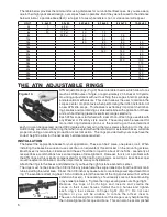
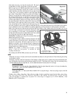
ATN adjustable rings
(Fig.10)
have rotatable inserts which allow for as
much as 20 Minutes of Angle, or approximately 20 inches at 100 yards,
mounting adjustment without touching the scopes internal windage
and elevation mechanisms. This in turn allows the user to maintain the
scopes center of optical axis when performing the initial installation of
a new ATN rifle scope. This feature is extremely important in eliminat-
ing parallax and maintaining a centered reticle with application of these
units, while offering greater overall zero range selectivity.
Each ATN scope is furnished with a set of non-offset rings useable with
any Weaver or Picatinny style mount. These may also be reversed for
more inter ring distance options or the recoil lug on the underside of
each ring can be reversed (turned 180 degrees) by removing the two screws attaching it to the ring.
Additionally, we offer an offset ring that when coupled with either standard or extended bases, will allow
proper mounting on most any production or custom action. The rings provided with your scope have the
correct height to allow for the necessary bell clearance required.
INstallatION
The Select the appropriate bases for your application. These can be 2 piece, one piece or rail. When
installing the bases be sure and use Locktite or an equivalent thread locker on the mounting screws.
Most bases install with 6-48 screws and these should be torqued to about 22 inch/lbs. Generally all
receiver/base combinations have some degree of misalignment. However, this is not a problem with
the ATN rings as this is easily compensated for by the floating ring inserts, assuring a stress free scope/
mount/receiver combination, another important accuracy consideration.
Attach the rings to the bases and determine if you have the right distance center to center.
The rings must not be closer than 1/8 inch to any place here the scope transitions from the 30 mm main
tube including the turret area. Closer than 1/8 inch may cause turret or variable power adjustment bind-
ing. The available offset ring has 1 inch of distance form the center of the ring and used with or without
extension base(s), if necessary, should easily cover all base mounting
or eye relief problems. Tighten the ring securing side nuts finger tight.
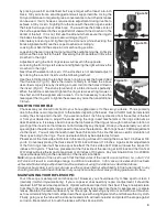
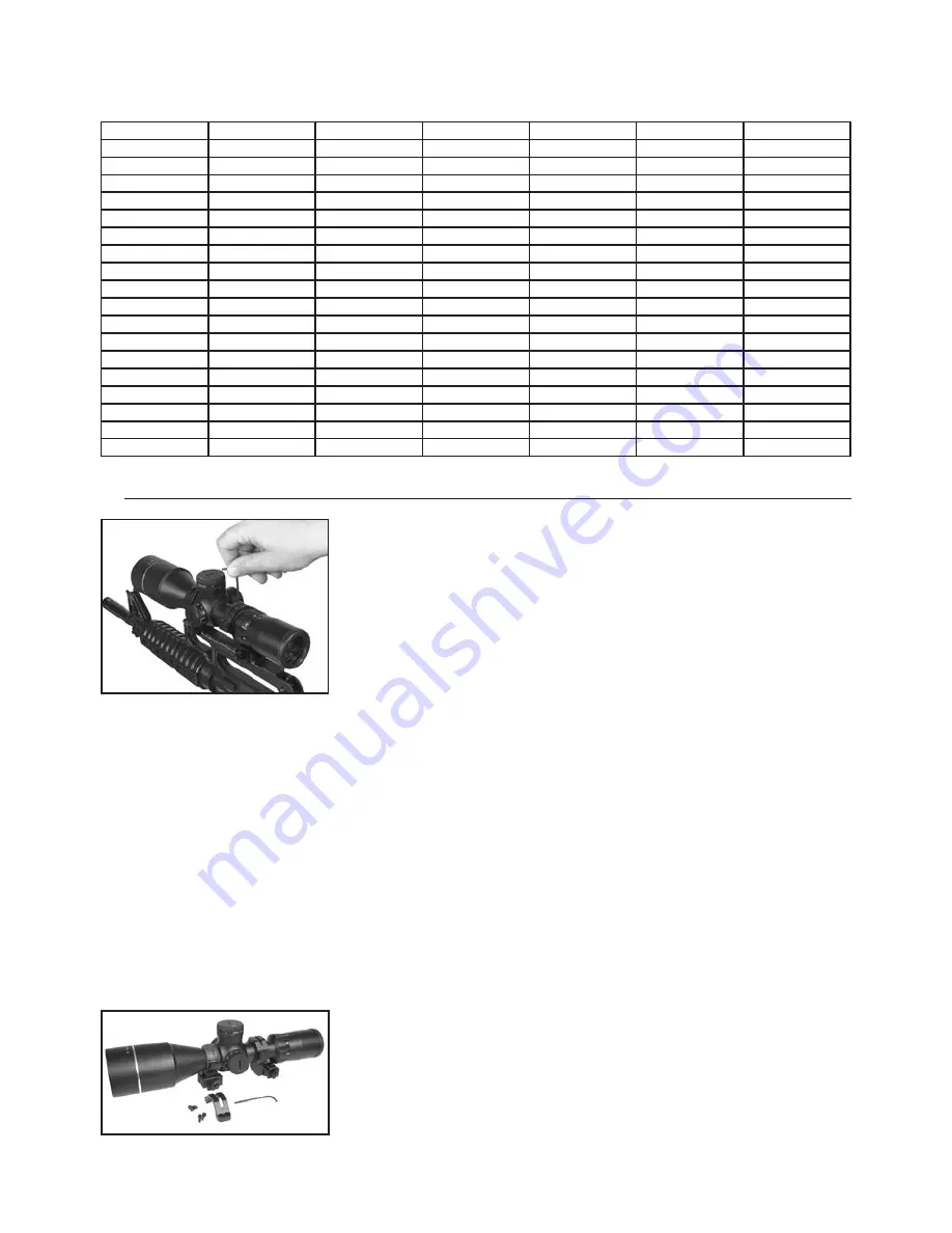
Remove the tops of both rings and inser ts and cradle the
scope in their lower halves. Install the top halves and tighten
each ring’s four screws to finger tight
(Fig.11)
. Do not over
tighten or you will be unable to rotate the of fset inser ts.
The use of a bore sight or collimator at this stage is very helpful setting
the initial alignment of scope and bore. This can also be accomplished
Figure 11
The table below provides the minimum focusing distances for our variable riflescopes. As you are aware,
due to their highly advanced design, our scopes have no parallax. But if they were focused to the distance
below minimal, a parallax-like effect (i.e. target in focus while reticle is not, or vice versa) will appear.
unIt
2-6x40
3-9x55
4-12x60
6-18x65
8-24x75
12-36x80
2x
1
4(3x)
4x
10
10(5x)
6
6x
20
17(7x)
20
12
8x
25(9x)
30
25
25
10x
60
50
50
12x
80
80
80
40
14x
115
115
50
16x
130
130
60
18x
150
150
70
20x
180
80
22x
200
90
24x
220
100
26x
110
28x
120
30x
130
32x
140
34x
150
36x
160
Figure 10.

