SAFETY AND MAINTENANCE MANUAL
1NO0024UK-09
40
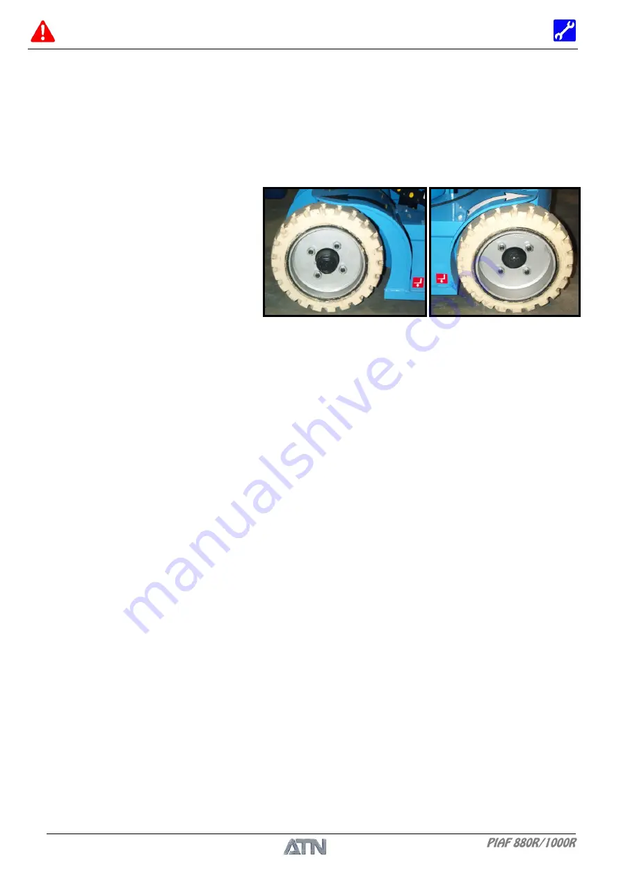
Front wheel
Rear wheel
1.1.1 OPERATING MODE
The hydraulic power is activated by pressing the validation pedal and moving one of the distributor
levers or the joystick. The translation speed is controlled by the varying speed gear motor which is
to be found on the upper control box. As soon as the platform rises, the speed limitation sensors
are activated and only the slow speed is available.
The steering is provided by a hydraulic cylinder controlled by moving the joystick.
1.1.2 WHEELS
A sound upkeep of the wheels ensures
satisfactory lifecycle of these wheels. It
is indispensable to check wear or tear-
offs, for if a wheel breaks, there is a risk
of serious even fatal injury.
DISMANTLING
1- Place the machine in a clean and uncluttered space.
2- Lower the mast and the arm completely.
3- Be sure that there is nothing in the basket.
4- Use an adequate lifting device to lift the chassis by at least 10cm. Shims capable of bearing the
weight of the platform must be installed. Set the chassis down again.
5- Unscrew the wheel nuts and take off the wheel(s).
- NB -
The 4 wheels are identical and therefore interchangeable.
REASSEMBLY
1- Fix the wheel(s) with the wheel nuts and tighten the nuts to 193Nm with a torque wrench
(cf. table: "Tightening torque for screws", Chap. II § 1.6).
1.1.3 WHEEL MOTORS
DISMANTLING
1- Place the machine in a clean and uncluttered space.
2- Lower the mast and the arm completely.
3- Be sure that there is nothing in the basket.
4- Dismantle the guards of the chassis.
5- Disconnect the batteries.
6- Locate, disconnect and close the hydraulic hoses of the wheel motor(s) (11).
7- Use an adequate lifting device to lift the chassis by at least 10cm. Shims capable of bearing the
weight of the platform must be installed. Set the chassis down again.
8- Unscrew the wheel nuts and take off the wheel(s) (23).
9- Remove the pin (27), unscrew the hub nut (12) and remove the bearing washer (13).
10- Dismantle the wheel hub (1) with a wheel-hub puller. Be careful of the key!
11- Unscrew the motor fixing nuts and screws.
12- Release the motor (11) by pulling it towards the inside of the chassis (5).
Summary of Contents for PIAF 1000R
Page 2: ...SAFETY AND MAINTENANCE MANUAL 1NO0024UK 09 2 DISTRIBUTOR STAMP...
Page 8: ...SAFETY AND MAINTENANCE MANUAL 1NO0024UK 09 8...
Page 11: ...SAFETY AND MAINTENANCE MANUAL 1NO0024UK 09 11 Chapter I USE AND SAFETY...
Page 12: ...SAFETY AND MAINTENANCE MANUAL 1NO0024UK 09 12...
Page 16: ...SAFETY AND MAINTENANCE MANUAL 1NO0024UK 09 16...
Page 22: ...SAFETY AND MAINTENANCE MANUAL 1NO0024UK 09 22...
Page 34: ...SAFETY AND MAINTENANCE MANUAL 1NO0024UK 09 34...
Page 36: ...SAFETY AND MAINTENANCE MANUAL 1NO0024UK 09 36...
Page 37: ...SAFETY AND MAINTENANCE MANUAL 1NO0024UK 09 37 Chapter II MAINTENANCE...
Page 38: ...SAFETY AND MAINTENANCE MANUAL 1NO0024UK 09 38...
Page 77: ...SAFETY AND MAINTENANCE MANUAL 1NO0024UK 09 77 3 13 ELECTRICAL DIAGRAM Diagram ref 1EL0023 01...
Page 78: ...SAFETY AND MAINTENANCE MANUAL 1NO0024UK 09 78 NOTES...


