background image


Confidential  Document 


©

 ATrack Technology Inc. All Rights Reserved.                                                                            Page 14 of 15 

5

5

.

.


A

A

p

p

p

p

e

e

n

n

d

d

i

i

x

x


5

5

.

.

1

1

.

.


H

H

a

a

r

r

d

d

w

w

a

a

r

r

e

e


S

S

p

p

e

e

c

c

i

i

f

f

i

i

c

c

a

a

t

t

i

i

o

o

n

n


Model Number 

AU7(UA) 

AU7(UE) 

AU7(UG) 

AU7(CV) 

AU7(CS) 

Dimensions (L x W x H) 

100 x 65 x 26 mm 

Weight 

155g   

Housing 

Aluminum alloy 

Operating Temperature 

-30

 ~ +80


25

 ~ +70


-40

 ~ +85


Electrical Characteristics 

Power Supply 

8V ~ 40V DC (±20%) 

Current Consumption 

Operating Mode : Max.100mA@12V, Deep Sleep Mode: 7mA@12V 

Backup Battery 

Internal 3.7V 950mAh rechargeable Li-ion battery 

Cellular Network Communication 

Technology 

UMTS/HSPA 

CDMA2000 1xRTT 

Frequency(MHz) 

850/1900 

900/2100 

800/850/900 

1700/1900/2100 

800/1900MHz 

Carrier Support 

EU/APAC 

US AT&T 

World Wide 

Verizon 

Sprint 

GSM/GPRS 

Quad-Band 850/900/1800/1900MHz 


N/A 

Cellular Antenna 

Internal Cellular antenna 

SIM Card 

1.8V/3V Micro SIM(3FF) 

N/A 

GPS 

Receiver 

66 Acquisition Channels, L1 Band, C/A Code, -165dBm sensitivity 

Accuracy 

3.0m CEP50 without SA 

Data Acquisition Rate 

1Hz 

GPS Antenna 

External GPS active antenna 

GPS Data Buffer Capacity 

8 MB 

Accelerometer 

3-Axis 

Z,X,Y 

Resolution / Sample Rate 

±16g, Max / 400Hz 

I/O Port 

ACC 

1 Positive Triggered 

Digital Input 


2 Positive, 3 Negative Triggered   

Digital Output 

3 Open-Collect Output (Max. sink current 300mA

MAX

Analog Input 

2 (0 ~ 40VDC/0 ~ 5VDC, 12 bits resolution)   

Multi-Purpose Port   

1 software configurable as either a digital output or an analog input 

1-Wire Interface


Supported up to 1 iButton

 and 4 temperature sensors 

Buzzer Output 

RS-232 Interface 

1 (Configurable Baud Rate 1200bps~115200bps)   

Audio Interface 

1 (Speaker and Microphone) 

Summary of Contents for AU7

Page 1: ...AU7 User Manual Revision 04 Revision Date 2016 03 28 ATrack Technology Inc 4F No 12 Wunhu St Neihu Dist Taipei City 11445 Taiwan R O C Tel 886 2 27975852 Fax 886 2 27974030 http www atrack com tw ...

Page 2: ...ing 3 2 Hardware 4 2 1 Package Content 4 2 2 Pin Assignments 5 2 2 1 Serial Cable JST Female Connector to DB9 Female Connector 5 2 2 2 Device I O Ports 5 2 3 LED Indications 7 2 4 Device Installation 8 3 Firmware Upgrade 9 3 1 Firmware Upgrade via RS232 9 4 AT IOCG Command Reference 13 5 Appendix 14 5 1 Hardware Specification 14 5 2 FCC Regulations 15 ...

Page 3: ...cue equipments ATrack Technology Inc is not liable for any loss or injury caused by using or referencing to any products Any possible means of using or integrating ATrack Technology Inc products shall be avoided 1 1 2 2 C Co op py yr ri ig gh ht t ATrack Technology Inc holds all parts of intellectual rights applicable in the copyright laws in all the countries Any or all parts of this document sha...

Page 4: ...c All Rights Reserved Page 4 of 15 2 2 H Ha ar rd dw wa ar re e 2 2 1 1 P Pa ac ck ka ag ge e C Co on nt te en nt t Each package contains the following device accessories Device 1 GPS Antenna 1 Serial Cable 1 GSM UMTS Antenna 1 Power IO Cable 1 ...

Page 5: ...car door open close detection and Panic Button in case of any emergency 3 Digital Outputs OUT1 OUT2 and OUT3 They are normally used for engine or ignition immobilization Please refer to our AU7 Quick Start Guide for details on how to set up relays for these applications These digital outputs are open collector type When in the ON state these outputs are grounded GND When in the OFF state it forms ...

Page 6: ...nology Inc All Rights Reserved Page 6 of 15 Family Code Model 01h DS1990A iButton 28h DS18B20 Temperature Sensor 16 pin male on board Power I O Connector 16 pin female Power I O Cable Compatible Devices Supported by 1 Wire Application ...

Page 7: ... signal Solid On Position get fixed GSM Red Off GSM module off 0 7 sec On 0 7 sec Off Searching for GSM signal 0 2 sec On 2 sec Off Registered to GSM network 2 blinks in every 2 sec Connected to GPRS network Continuous blinking SIM PIN Error Note In the case of SIM PIN Error the device will check the AT SPIN every 10 minutes and try to access the SIM again The PIN will be validated 3 times and if ...

Page 8: ... are used to determine the status of harsh driving events If the following installation is not practicable it is advised to use the GPS for detecting harsh driving as an alternative 1 Note When installing the device the vehicle should be parked on a horizontal place not tilted Then the device should be installed parallel to the vehicle body and fixed with a mounting bracket or double sided adhesiv...

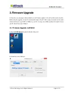
Page 9: ... serial connection Before doing the upgrade connect the serial cable between the JST XHP 4 output connector and the serial communication port e g COM1 or COM2 on your PC You may use a USB to serial port converter in case your PC doesn t have any COM port 3 3 1 1 F Fi ir rm mw wa ar re e U Up pg gr ra ad de e v vi ia a R RS S2 23 32 2 1 Run the ATFWUpload program by double clicking on it 2 Select t...

Page 10: ...Document ATrack Technology Inc All Rights Reserved Page 10 of 15 3 Set the console baud rate to 57600 4 Un tick the check box next to Rest Parameter 5 Click on the button to browse the firmware file where you saved ...

Page 11: ...ack Technology Inc All Rights Reserved Page 11 of 15 6 Select the firmware file AU7_0 06 dat Click on the Open button 7 Click on the Open button and power on the AU7 In this example the AU7 is connected to a DC 12V power supply ...

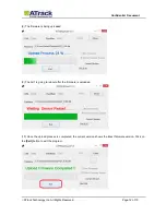
Page 12: ... Reserved Page 12 of 15 8 The firmware is being uploaded 9 The AU7 is going to reboot after the firmware is uploaded 10 Once the upload process is completed the current version shows the latest firmware version Click on the Exit button to exit the program ...

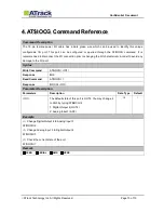
Page 13: ...onnect the I O connection prior to changing the I O characteristic in order to avoid any damage to the I O port Syntax Write Command AT IOCG IO1 Response OK Read Command AT IOCG Response IOCG IO1 Parameter Description Parameters Description Data Type Default IO1 The default state of this port is OUT4 You may change it to AN3 by typing AT IOCG 2 1 Digital Output 4 OUT4 2 Analog Input 3 AN3 U8 1 Exa...

Page 14: ...PAC US AT T World Wide Verizon Sprint GSM GPRS Quad Band 850 900 1800 1900MHz N A Cellular Antenna Internal Cellular antenna SIM Card 1 8V 3V Micro SIM 3FF N A GPS Receiver 66 Acquisition Channels L1 Band C A Code 165dBm sensitivity Accuracy 3 0m CEP50 without SA Data Acquisition Rate 1Hz GPS Antenna External GPS active antenna GPS Data Buffer Capacity 8 MB Accelerometer 3 Axis Z X Y Resolution Sa...

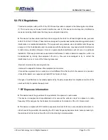
Page 15: ...ce to radio or television reception which can be determined by turning the equipment off and on the user is encouraged to try to correct the interference by one or more of the following measures Reorient or relocate the receiving antenna Increase the separation between the equipment and receiver Connect the equipment into an outlet on a circuit different from that to which the receiver is connecte...

Reviews: