


4
April 2005
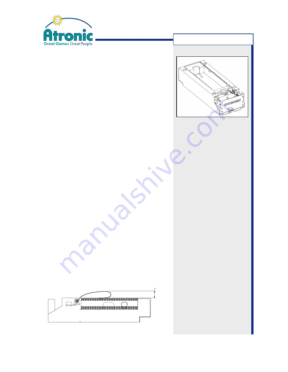
Ticket Printer Ithaca
®
850
Ithaca 850 - Technical Data
Dimensions:
Height:
67.6 mm (2.66")
Width:
113.3 mm (4.46")
Depth:
285.8 mm (11.25")
Weigth:
2.4 kg (5.3 lbs)
Printer type:
Fixed 2.25" linear thermal head
Printer life:
20 million print lines
Print speed:
max. 125 mm/sec. (text mode)
Resolution:
203 x 203 dpi, 136 x 203 dpi
Interface:
Bi-directional, serial RS-232
Environmental conditions
Operating temperature range:
0° - 40°C (32° - 77°F)
Storage temperature range:
-10° - 50°C (14° - 122°F)
Operating humidity range:
10% - 90% noncondensing
Power requirement: 24 V DC, max. 2.2 A
Ticket specification
Dimensions
Width:
65 ± 0.75 mm (2.56 ± 0.03")
Length:
156 ± 1 mm (6.14 ± 0.04")
Thickness:
114 microns (0.0045")
Weigth:
102 g/m²
Ticket type:
Kanzaki TO-381N or approved equivalent
Thermal sensitive layer facing down
Fan folded stack of 200 tickets
Ticket clearance
A minimum paper clearance of approx. 20 mm (0.75")
is required above the printer's ticket bucket. Consider
this when installing online system equipment to a
machine top box where a printer is installed.
20 mm
T
ECHNICAL
D
ATA


