5
MANU3610-01
INSTALLATION
The Series 3610 is an environmentally sealed device; therefore all cables supporting the peripheral devices,
communications and power sources must be inserted through the appropriate watertight connectors. Observance to
this requirement will ensure watertight integrity and protection against external elements.
Mounting
: The case and hinged front cover are made from durable fiberglass polyester. The sealed terminal
comes with four plastic mounting ears. These ears should be secured to the bottom underside of the enclosure
and extend out from the sides to allow for wall mounting. A special mounting plate is available if an
integrated reader is purchased.
Cabling
: A twisted pair or category 5 style
round
cable is required. Select the appropriate seal tight
connectors and remove the nylon plugs to accommodate data transmission and 12VDC power pack cable
assemblies. The cable is passed through the seal tight connector that is then tightened down over the cable.
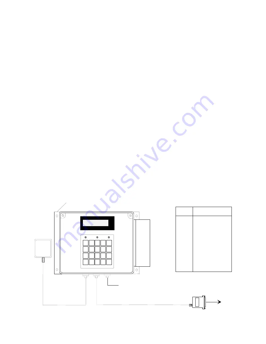
One seal tight connector per cable is allotted (see diagram below). The supplied rubber tubing should be slid
over any cable if the seal tight connector does not clamp the cable securely. This should be done before
tightening the connector.
Power
: When terminal power is being supplied locally, insure that a conventional 110VAC-wall outlet,
220VAC in Europe and other areas, (check local electrical code requirements) is available to accept the Series
3610 power pack assembly. The outlet should be no further than four (4) feet from the terminal.
Base
: Locate a flat wall surface to accommodate the Series 3610. Typical mounting height is forty-eight
inches from floor to the terminal display (Compliant to the Americans with Disabilities Act). Observe OSHA
and/or local safety codes when operating tools during all phases of installation. Attach the four terminal
mounting ears (or mounting plate) to a flat wall surface.
For RS232 communication applications, one end of the communication cable terminates into the Series 3610
communication port while the other terminates into the host computer’s serial port via an ATS RS232
Communication Adapter. For remote powering, a Network Junction Box or Network Junction Box Jr. could be
used.
RS232 INSTALLATION
COMM ADAPTER
DB25-RJ45 W/PWR
TO HOST
ATS
POWER
SUPPLY
ACCU-TIME SYSTEMS
ELLINGTON, CT
LOW
POWER
INVALID
VALID
1 2
3
4 5
6
7 8 9
0
CLEAR
ENTER
F1
F2
F3
F4
F5
F6
F7
F8
External
Reader
Mounting
NOTE: Pinouts are referenced to the terminal
Pin # Description
1
2
3
4
5
6
7
8
Earth Ground
Receive
Transmit
N/C
N/C
Ground
+VDC
Ground
Reader Port
Mounting Plate
Assembly


