background image


MANU3610-01 

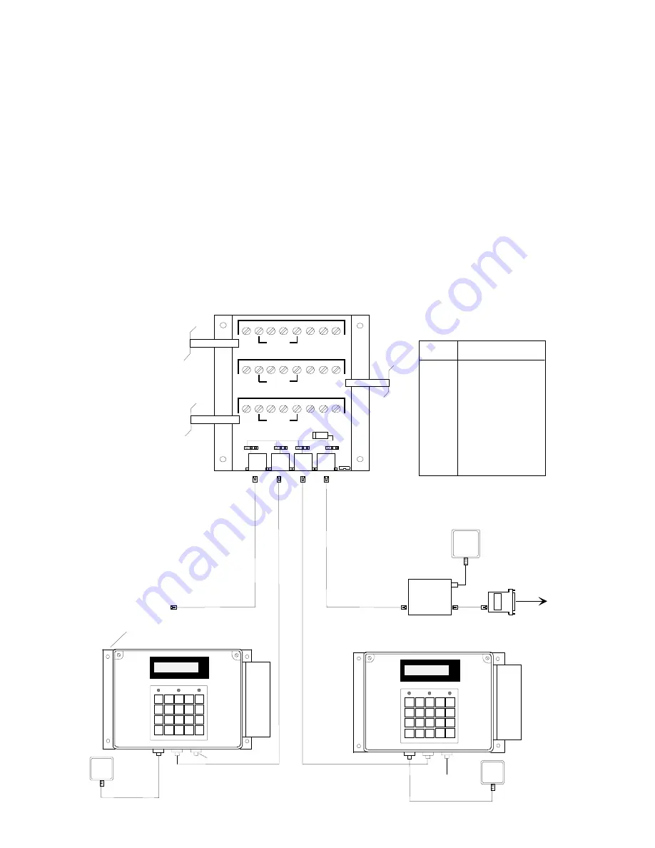
For RS485 Communication applications, ATS

 recommends using a 

round

 data transmission cable that adheres to 

the following specifications: 


Five conductor shielded 24-gage wire with a drain. 


The impedance of the cable should be 100 Ohms. 


The capacitance should be 12 pico-farads per foot. 


The jacket of the cable is typically PVC material. 


Note

: If the host is not equipped with an RS485 port, an ATS

 RS232/485 Converter with a 12-volt power pack 

assembly will convert the terminal communication lines to RS232 levels. The host output of the RS232/485 
Converter plugs directly into the ATS

 RS232 Communication Adapter. 

 
RS485 allows for the Series 3610 to be used in multi-dropped networks. Thirty-two (32) terminals can be 
supported on a single host communication port. The use of ATS

 Series 1000 Network Controllers allows up to 

five hundred and twelve (512) terminals on a single host communication port. 


12 VDC
POWER

SUPPLY

MULTI-CLOCK - RS485  INSTALLATION

COMM ADAPTER

DB25-RJ45 W/PWR

TO HOST

NETWORK CONTINUED

RS-232 TO

RS-485 

CONVERTER

ACCU-TIME SYSTEMS

ELLINGTON, CT

LOW

POWER

INVALID

VALID

1 2

3

4

5

6

7 8

9

0

CLEAR

ENTER

F1

F2

F3

F4

F5

F6

F7

F8

ATS

POWER

SUPPLY

External

 Reader

Mounting

ACCU-TIME SYSTEMS

ELLINGTON, CT

LOW

POWER

INVALID

VALID

1 2

3

4

5

6

7 8

9

0

CLEAR

ENTER

F1

F2

F3

F4

F5

F6

F7

F8

ATS

POWER

SUPPLY

External

 Reader

Mounting

Reader Port

NOTE: Pinouts are referenced to the terminal

Pin #       Description

1
2
3
4
5
6
7
8

Earth Ground
DI -
DO +
DO - 
DI +
Ground
+VDC
Ground

Reader Port

1

2

3

4

5

6

7

8

COMM

E.

G

N

D

P.GND

+V

D

C

P.GND

JP1

D R O P  2

DR OP 3

D C   PO W E R

E. GN D

1

2

3

4

5

6

7

8

CO M M

E.

G

N

D

P.GND

+V

D

C

P.GND

1

2

3

4

5

6

7

8

CO M M

E.

G

N

D

P.GND

+V

D

C

P.GND

D R O P  1

D R O P  4

NC

NO

N C

N O

JP2

JP3

JP4

Trunk Wire

Network Cabling

Mounting plate

 assembly

Summary of Contents for Accu-Time 3610 Series

Page 1: ...M ME EN NT TA AL LL LY Y S SE EA AL LE ED D T TI IM ME E A AN ND D D DA AT TA A C CO OL LL LE EC CT TI IO ON N T TE ER RM MI IN NA AL L Accu Time Systems Inc 420 Somers Road Ellington CT 06029 Tel 860...

Page 2: ...this manual may be reproduced or distributed in any form or by any means or stored in any database or retrieval system without Accu Time s prior written permission Accu Time Systems Inc makes no warr...

Page 3: ...3 MANU3610 01 ACCU TIME SERIES 3610 TABLE OF CONTENTS Introduction 1 Features 2 Specifications 3 Installation 4 ACCU RATE Diagnostics 9 Maintenance 14 Troubleshooting Guide 15 MANU3610 01 01...

Page 4: ...s can provide users with the flexibility to create a variety of options Reliability A Real Time Clock RTC provides 12 or 24 hour time formats with quartz precision An optional uninterruptible power su...

Page 5: ...ard RS232 or RS485 compatible On board ACCU RATE terminal set up and diagnostics package Custom keypad legends with software defined function keys Large 20 key tactile 4x5 matrix keypad 4 line x 20 ch...

Page 6: ...DI DO port and Auxiliary Serial Interface port Enclosure Molded fiberglass polyester sealed environmental housing for indoor outdoor use NEMA 4X approved Power 10 to 17VDC 12VDC 250 milliamps Nominal...

Page 7: ...lity up to 110 and down to 10 Fahrenheit With a second heater option the temperature range expands to 25 Fahrenheit The terminal should be mounted on a vibration free area Select a location which has...

Page 8: ...one before tightening the connector Power When terminal power is being supplied locally insure that a conventional 110VAC wall outlet 220VAC in Europe and other areas check local electrical code requi...

Page 9: ...e use of ATS Series 1000 Network Controllers allows up to five hundred and twelve 512 terminals on a single host communication port 12 VDC POWER SUPPLY MULTI CLOCK RS485 INSTALLATION COMMADAPTER DB25...

Page 10: ...the Series 3610 The supplied rubber tubing should be installed if the seal tight connectors do not properly secure either cable Place the jumper located at JP1 on the I O board to the NC position Figu...

Page 11: ...D P GND VDC P GND JP1 JP2 DC POWER RS232 485 Communication Board J1 J2 Figure 2 If power is not supplied through the communication cable plug power into PJ1 Ensure that the jumper JP1 is placed in the...

Page 12: ...he CLEAR key the user can step through the selections NOTE Test mode may be exited at any time by placing the Test Use switch back to the Use position and pressing the CLEAR key SELECTIONS ATS TEST MO...

Page 13: ...The message KEY INPUT ACCEPTED is displayed Each time the ENTER key is pressed an internal test of the terminal s communication port is performed If an error is detected the message COMM PORT FAIL wi...

Page 14: ...ed press the ENTER key to store the value and advance to the next parameter Address To change the terminal address 1 Press the CLEAR key to increment the address values from 01 to 32 2 When the desire...

Page 15: ...S ENTER TO RETEST To perform the local communication loop back place the Test Use switch back to the Test position and press the ENTER key The following message should appear NETWORK TEST PASS ENTER T...

Page 16: ...ARING MEMORY The green Valid LED will blink and the terminal will execute its power up sequence and return to the beginning of the Test Mode ATS AUX PORT TEST The ATS AUX PORT TEST will automatically...

Page 17: ...n device The only required procedure is periodic cleaning of the badge reader To clean the badge reader swipe a pre moistened isopropyl alcohol cleaning card through the reader several times Low usage...

Page 18: ...to the terminal blanking out Solution Check output of 12 volt DC power pack Solution Check for proper AC outlet voltage Possible cause Terminal does not go blank after unplugging the battery connector...

Page 19: ...supervisor Possible cause Keypad connector is unplugged Solution Test keypad in the ACCU RATE test mode If all solutions have been explored and the problem still exists contact the Accu Time Product S...

Page 20: ...ar installation If this equipment does cause harmful interference to radio or television reception which can be determined by turning the equipment off and on the user is encouraged to try and correct...

Reviews: