7
OPERATING INSTRUCTIONS
Your ATS UV System is equipped with the ATS-280CB UV Lamp Detector and Timer circuit board
which is designed to provide a continuous monitoring system of the UV lamp operational status. This
solid state electronic circuit board provides the latest in UV lamp monitoring technology.
UV LAMP / CONTROL BOX START UP PROCEDURE - (4 Step Process)
1. Make sure the UV lamp is inserted per instructions into the quartz sleeve and UV chamber. Then
plug the UV lamp into the lamp connector.
2. Plug the electrical control box into a 120volt wall plug outlet.
3. Upon start up the UV lamp Detector and Timer circuit board will perform a self diagnostic test.
When power is applied the UV lamp will go on and a circuit board output check is performed as follows:
• Quick Beep
• Green LED on, then off
• Red LED on, then off
• Solenoid / Relay connection on, then off
• Pause with beeps
• Green LED on = System Check OK, UV System is operational.
4. Set the 1 Year Lamp Timer – WITH NEW UV LAMP –
Make sure the control box is plugged into the wall outlet and the UV lamp is on. Press and hold the reset
push button. A tone that descends in frequency once per second will be heard. Hold the reset button
down for approximately 5-8 seconds until you hear a continuous tone. At this point release the button.
The 1 year lamp timer has just been reset.
UV lamp Detector and Timer circuit board Lamp Operation and Alarm features:
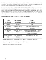
• UV System OK – Green LED will flash every 5 - 10 seconds.
• 30 Days remaining on Lamp Life – Flashing Yellow LED with an intermittent audible tone.
• End of Lamp Life- Flashing Red LED with an intermittent audible tone.
• Lamp Out- Continuous Red LED with a continuous audible tone.
• If your UV System has a 120Vac Normally Closed Solenoid Valve or Remote Alarm connected to
the UV Unit plug-in connection, this will activate at End of Lamp Life or Lamp Out alarm condi-
tions.
To Silence the Audible Alarm with Snooze Button:
1. 30 Days remaining on Lamp Life Alarm - Push reset button – Silences the audible tone for two
weeks while the Yellow Led continues to Flash. (You can Silence audible alarm 2 times Max.) You
have up to 30 days to replace the lamp.
Service Unit - Replace the UV Lamp within 30 Days.
2. End of Lamp Life Alarm - Push reset button- Silences the audible tone for one week while the RED
LED continues to flash. (You can Silence audible alarm 4 times Max.)
Service Unit Immediately - Replace the UV Lamp.
3. Lamp Out Alarm- Push reset button- Silences the audible tone for one week while the continuous
Red LED stays on. (You can Silence audible alarm 1 time only.)
Service Unit Immediately - Replace the UV Lamp.
Summary of Contents for DWS-15
Page 6: ...6 ATS 280CB RESET BUTTON MOUNTED UNDER TOP PLATE OUTLET MAINS BALLAST LAMP...
Page 19: ...19...
Page 20: ...20 WIRING DIAGRAM...
Page 21: ...21 ATS1 421 CCASE WH 3C DWS 15 DWSW 15...
Page 22: ...22 ATS1 421 CCASE WH 3C...
Page 23: ...23...
Page 24: ...24 ATS1 421 WH 3C...
Page 25: ...25...
Page 26: ...26...
Page 27: ...27 DRAWING AND PART NUMBERS...
Page 28: ...28 DWS 7 Explosion...
Page 30: ...30 DWS 15 Explosion...
Page 32: ...32 SE 7 Explosion...
Page 34: ...34 SE 15 Explosion...
Page 36: ...36 DWSW 8 Explosion...
Page 38: ...38 DWSW 15 Explosion...


