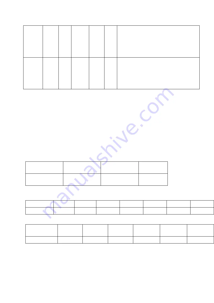
0=TIMED SEQUENCE CONTROL
1=DEW POINT CONTROL SENSOR TYPE 1
2=DEW POINT CONTROL SENSOR TYPE 2
3=REMOTE CONTROL
P5
0
0
1
1
Type of REMOTE CONTROL.
0=normally open contact
1=normally closed contact
HOW SET CONTROLLER IN TIMED SEQUENCE CONTROL
If the real flow on the dryer is lower than nominal flow, the end user can reduce the
air purge changing parameter P1. Do not change P2 if not agreed with the
manufacturer.
P1
3 default
6 / 9
9 / 18
Real Flow %
100 / 85 %
85 / 70 %
70 / 50
To calculate Real Flow % use the follows instructions:
Correction factors for working pressure
Pressure Bar 4
5
6
7
8
9
10
Factor P
0,63
0,75
0,88
1
1,14
1,25
1,39
Correction factors for inlet temperature
Temperature
°C
25
30
35
40
45
50
Factor T
1
1
1
0,97
0,88
0,73
Real Flow % = Max real Flow / Adjusted Nominal Flow
Adjusted Nominal Flow = Nominal Flow x Factor P x Factor T
Summary of Contents for HGL 120
Page 17: ...B Schemat przep ywu powietrza...
Page 18: ...C Wymiary osuszacza...
Page 20: ...D Schemat elektryczny...
Page 21: ...E Widok rozstrzelony...
Page 23: ...DESICCANT DRYER Instruction and Maintenance Manual...
Page 24: ...HGO 40 160 HGL 40 160...
Page 27: ...B Flow diagram C Dryer dimensions D Wiring diagram E Exploded view F Suggested spares...
Page 41: ...LIST OF ATTACHMENTS...
Page 44: ...A C IN L E T O U T L E T IN L E T E B F G D MODEL 40 80 120 160 INLET OUTLET INLET...
Page 46: ...D WIRING DIAGRAM C CONTROLLER EMV 1 EMV 2 EMV 3 EMV 4 EMV ELECTROMAGNETIC VALVE...


