background image

11/10/


NOT

Thre
 
Plea
custo
the e

 
WAR

Exha
injec

/2008 

TE:

  Among

ad) tap and

se read all 

omer, pass 

end. 

RNING:

  Th

aust Gas Te

ction (mixtur

Please rea

Figu

 other stan

d a 21/64" d

instructions

this manua

he ATS Wat

emperature

res of wate

Installatio

Water 

All mak

ad all instr

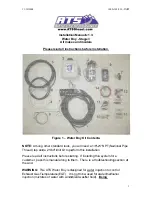
ure 1 – Wa

dard tools, 

drill bit to pe

s before sta

al along to t

ter Boy is d

e (EGT).  It 

r with winds

on Manual

Boy - Stag

es and mo

ructions be


ater Boy Ki


you will ne

erform this 

arting.  If in

them.  The

designed fo

is not to be

shield wash

l v1.3: 

ge 3 

odels 

efore insta

t Contents

eed a 1/8"-2

installation

stalling this
re is a troub

r water inje

e used for w

her fluid).  

U

1000-


llation. 

s


27 NPT (Na

s system fo

bleshooting

ection to co
water/metha

Using 

-102-930 - INS

ational Pipe

r a 

g section at

ntrol 

anol 

ST 

1


Summary of Contents for Water boy

Page 1: ...drill bit to pe s before sta al along to t ter Boy is d e EGT It r with winds on Manual Boy Stag es and mo ructions be ater Boy Ki you will ne erform this arting If in them The designed fo is not to...

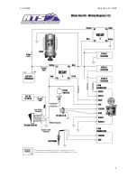
Page 2: ...active The third stage will activate when the EGT probe senses a temperature above the box setting AND the boost sensor measures approximately 15 psi or 30 see Boost Level Setting section of boost or...

Page 3: ...k that no other vehicle systems are damaged during installation Installation 1 Please make sure no parts are missing from ATS Stage 3 WaterBoy Kit A complete corresponding list of parts can be found o...

Page 4: ...the switch with the spade connector Connect the other end of the black wire to a good ground under the dash 16 Connect the supplied Pink wire to the remaining switch terminal and attach it to a 12V s...

Page 5: ...ebris holes in th ind that the good dista zzles Make assenger s pport Dura e pump to a y harness a y 1 Conne assembly a ware Relay 2 la battery Cu onvenient l Relay 1 la battery Cu onvenient l ires to...

Page 6: ...onnecto m the T to ot have a s the 21 64 d ting before ctronics boa st line fitting 31 d intake ma Ford 6 0L m T tings on the lent size and po ds quire a boos oft 1 8 line ors then sp the boost p soft...

Page 7: ...area so it is easy to check and clean in the future 35 Run 3 8 line from the filter to the tank 36 With the tank in place and 3 8 lines installed route the Red harness wires labeled To Tank along the...

Page 8: ...nk check for leaks 40 Reconnect the battery s 41 Test drive the vehicle with the system armed The LED will be green when armed yellow during stage 1 orange during stage 2 and red during stage 3 42 In...

Page 9: ...11 10 2008 1000 102 930 INST 9...

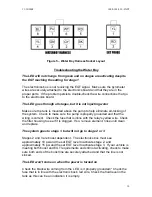
Page 10: ...hat the wiring is correct Check the fuse that is inline with the relay s yellow wire Check the filter housing to see if it is clogged If so remove element rinse until clean and replace The system goes...

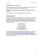
Page 11: ...Body and ATS High Performance Transmission along with our full line of power enhancers Please call or e mail our Technical Service Department 8 00am to 5 30pm Mountain Standard Time Monday through Fri...

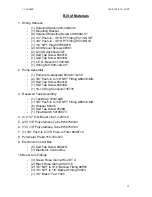
Page 12: ...NPT Fitting A6MC6 MG 4 Self Tap Screw 85241D 1 Self Tap Screw 84930D 1 16 14 Ring Connector 35776 3 Reservoir Tank Assembly 1 Tank Cap 070316AE 1 3 8 Push In to 3 8 NPT Fitting A6MC6 MG 6 Washer 88445...

Page 13: ...ng HSR316 1 ATM Fuse Holder ATMFH12 1 15A ATM Fuse ATM15 1 Switch 3 Female Blade Connectors 86061 4 18 AWG Wire Black GPT 18 00 4 18 AWG Wire Pink GPT 18 11 1 16 14 Ring Terminal 25262 13 Nozzle Bundl...

Reviews: