background image

8

Safety Instructions

Obligations

Obligations of the Operator/manager:

The Zirocco-M100 must only be operated by personnel with the following knowledge:

x

Are aware of the basic workplace safety information and accident prevention regulations.

x

Have been instructed and trained in working with the Zirocco-M100.

x

Have read and understood this operating manual. 

The operator is obliged to as follows: 

x

To ensure that the required service and maintenance is performed according to the instructions laid out 
in this operating manual.

x

To keep all the warning pictograms on the machine in a legible state.

If you still have queries, please contact the representative or manufacturer.

Obligations of the Operator:

Before starting work, all operators are obliged to as follows:

x

To comply with the basic workplace safety instructions and accident prevention regulations. 

x

To read and understand the operating section of the operating manual. 

x

To use the required personal protective equipment, when working with the Zirocco-M100.

x

To read the section "Warning symbols and other labels on the machine" in this operating manual, and to 
follow the safety instructions represented by the warning symbols, when operating the machine.  

x

To get the required work training.

If the operator discovers that a function is not working properly, he must eliminate the fault immediately. If 
this is not the task of the operator or if he does not possess the appropriate technical knowledge, then he 
must report this fault to his superior (supervisor).

Summary of Contents for Zirocco-M100

Page 1: ...Operating Manual Zirocco M100 Jet Dryer Cleaner...

Page 2: ...ons 16 Before start up 17 Safety Stop 17 Power Up 18 Shut down and Cooling 20 Parking and storage 21 Display shut down 21 Re fuelling 21 Low Fuel Level 22 Change Filter Indication 22 Air filters Tradi...

Page 3: ...3 Battery replacement 34 Wheels 34 Replacement of wheels 34 Igniter Replacement Guide 35 Storage Transportation 38 Wastedisposal 38...

Page 4: ...DIRECTIVE 2006 42 EC OF THE EUROPEAN PARLIAMENT AND OF THE COUNCIL of 17 May 2006 on machinery The EMC Directive 2004 108 EC Person authorized to collect technical data and make them available to the...

Page 5: ...04 2006 Safety of machinery Electrical equipment of machines General requirements DS EN ISO 13849 1 2006 Safety of machinery Safety related parts of control systems General principles for design ISO 1...

Page 6: ...lated to an environmental noise level as weighted average of the different work steps during machine operation It is the maximum sound pressure which the operator will experience when using the machin...

Page 7: ...is table the LWA value is used in the calculation of the TWA dose as a worst case although the operator normally would operate the machine at lower performance level because the marking equipment ofte...

Page 8: ...ve or manufacturer Obligations of the Operator Before starting work all operators are obliged to as follows x To comply with the basic workplace safety instructions and accident prevention regulations...

Page 9: ...work areas with limited air exchange respiratory protection or a limited use can be necessary to apply A backup operator needs to be present where oncoming traffic is not shielded from the working ar...

Page 10: ...g removal Concrete drying Crack repair This Operating Manual utilise the following safety signs Follow these safety signs carefully since failure to comply may cause personnel injuries or irreparable...

Page 11: ...and instructions in this document conform to the rules and provisions in the EU Machinery Directive 2006 42 EC and Directive 2004 104 EC INFORMATION This Operating Manual is subject to change without...

Page 12: ...jects Independent and convenient machine operation as there is no need for a compressor or bottled gas supply The Zirocco M100 is equipped with a gas turbine which operates on standard diesel type EN5...

Page 13: ...ay 2 Turbine module box 3 Fuel tank 4 Cyclone separator 5 Turbine cover 6 Gas Spring w adjusting lever 7 Battery 8 Battery cover 9 Nozzle available in various designs and widths 10 Nozzle Cover Shroud...

Page 14: ...7 Safety stop Flashes red when the safety stop is enabled 8 Start up Wait Flashes when the turbine is heating up 9 Temperature indication 10 Operational hours Display page 2 Page 2 Display Page 2 1 A...

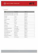
Page 15: ...25 m2 5000 90 Battery 60 Ah 4000 10 Display DP 250 1000 10 Standard Nozzle 300 mm 2000 280 Labels ATT Logo 9000 30 Label Heat Warning sign 9000 20 Label Hearing protection Warning sign 9000 10 Turbine...

Page 16: ...least 5 m from the machine during operation Hearing and eye protection The personnel in the immediate vicinity of the Zirocco M100 must use hearing protection and safety goggles when operating the Zi...

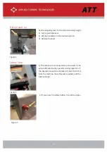
Page 17: ...3 Release the lever Safety Stop Operating the machine Figure 2 1 The safety wire is connected to a stop switch The wire is attached to the operator during operation If the operator moves to a distance...

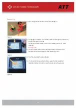
Page 18: ...conds The key will automatically return to the middle position 1 when released See Figure 10 3 The pre heater symbol in the display will flash and the current temperature will be displayed when above...

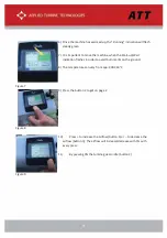
Page 19: ...indication flashes in order to avoid burn marks on the ground 8 The temperature can vary from app 400 460 C Figure 8 9 Press the button 2 to get on page 2 Figure 9 10 Press to increase the airflow bu...

Page 20: ...nd then start a cooling program will cool down until below app 50 C The Zirocco M100 can be restarted once the display shows the text Ready to Start again Figure 11 2 When the key is turned to the lef...

Page 21: ...ogram is completed and the operating symbol on the display has been off for 2 minutes The Zirocco M100 turns off automatically after 60 minutes factory setting The timer can be set from 20 to 60 minut...

Page 22: ...tion or when worn out 2 Switch off the machine before replacing the filters Use only filter type ATT 5000 60 Then change the filters and turn the key to the left to reset the warning 3 This indication...

Page 23: ...ter maximum 10 hours of operation 4 When prompted to change filter or if the filters are not serviceable then follow the step in Figure 19 Change filters Figure 19 1 Pull out and remove the filter hol...

Page 24: ...the section Safety Instructions Fuel US specifications 1 D S15 ULSD Fuel capacity 31L 8 2 US Gallons Fuel consumption 25 35 L h 7 9 US Gallons h Battery 12V AGM 60 Ah Box size L02 min 100A Generator...

Page 25: ...25 Dimensions...

Page 26: ...26...

Page 27: ...figure Each hazard zone requires its own protection measures x The NOISE zone requires protection to avoid loss of hearing ability x The EXHAUST zone where the use of safety glasses are required x Th...

Page 28: ...otection Caution the nozzle cover can still be warm after the turbine has cooled down Order immediately new warning signs if the old ones get damaged Warning signs can be ordered via ATT or Distributo...

Page 29: ...vel The fuel level symbol flashes red Fill up with fuel Wait 2 minutes to get CANBUS updated Safety switch activated Reset safety switch Turbine will not start after repeated attempts Contact ATT supp...

Page 30: ...the cyclone separator 2 Loosen the quick releases on both sides of the heat shield 3 Lift and remove the heat shield 4 Loosen the quick releases on the turbine module box cover on both sides 5 Remove...

Page 31: ...Remove the air filters 8 Check the air filter for dirt penetration or any damage 9 Replace if worn out and ensure that the edges of the air filters are aligned with the filter frame 8 Check for air b...

Page 32: ...full functionality T Turbine e Module e Box x Replacement t 1 Remove the cyclone separator 2 Loosen the quick releases on both sides of the heat shield 3 Lift and remove the heat shield 4 Remove the...

Page 33: ...move dust and dirt incl bitumen leftovers etc Check the Air Filters Replace if dirty or showing signs of tear Check fuel level in the display Refuel if necessary premix in a plastic cannister 1 12V V...

Page 34: ...and wear It is recommended that they are replaced as soon as they show signs of damage New wheels and other spares and accessories can be ordered via our distributors see more on our website https zir...

Page 35: ...bine generation is the ability for the operator to change the turbine igniter It was earlier required to stop the operation and send the turbine back to ATT for service The igniter is now placed acces...

Page 36: ...s jet turbine Unclick the electrical wire by pressing on the sides of the connection Unscrew the igniter Be careful to keep the flat O ring sealing in place on the igniter Be careful not to forget abo...

Page 37: ...ound cable from the turbine cover and tighten it by hand without using tools Reconnect the igniter wire After connecting the igniter the igniter and grounding wire are stripped together to keep them f...

Page 38: ...ATT ATT recommends the use of our Nozzle Protection to avoid getting dust and dirt in the turbine when not in use both on the work site and in the storage facility Nozzle protection Item number 14000...

Page 39: ...Applied Turbine Technologies Telephone 45 70236080 E Mail info zirocco dk or support zirocco dk Website www zirocco dk...

Reviews: