19
Link collector
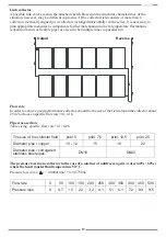
A possible link can be seen in the attached sketch. Based on the structural characteristics of the
situation, however, may be different in practice. If the collector field consists of more than 6
collectors (vertically aligned) or 4 collectors (arranged horizontally) in the series, it is necessary to
plan appropriate measures to compensate for thermal expansion due to temperature fluctuations
(expansion bends or flexible pipe) or a field to be multiple times in parallel run.
Output
Reverse
Flow rate
In order to achieve good performance collector,
should be the size of the field around the collector about
25 m² to choose a specific flow rate 30 l / m² h.
Pipe cross-section
Table sizing, specific flow rate 30 l /
m
2
h
The size of the collector field
Diameter pipe / copper
Diameter pipe / corrugated
stainless steel pipes
pribl. 5
10 - 12
DN16
pribl. 7,5
15
pribl. 12,5
18
DN20
pribl. 25
22
The pressure loss in one collector in the case of a mixture of antifreeze agent / water (40% / 60%)
where the heat transfer fluid temperature 50 ° C.
Pressure loss curve:
p = 0,0000106x² + 0,0137580x
Flow rate
Pressure loss
0
0,7
0
50
1,5
100
150
2,3
3,2
200
250
4,1
5,1
300
350
6,1
7,2
400
450
8,3
9,5
500


