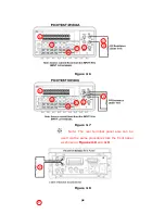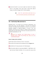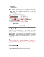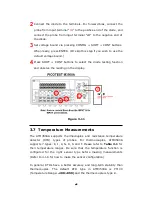
6
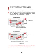
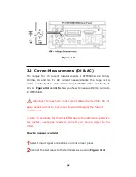
Connect test leads to your source signal and observe the reading
shown on the display. If the input signal is beyond the allowed
range, an overflow message “OVLD” will be displayed.
※
Note: The rear terminal panel also can be
used via the same procedures as the front panel.
3.5 Continuity Measurements
ATM3500A uses 1 K Ω range for the continuity measurement. The
meter beeps when the test resistance is less than the threshold
resistance. The default threshold resistance is 10Ω, but you can set the
threshold resistance to anything between 1 Ω and 1 K Ω. The
resistance value set by you is stored in a volatile memory and will be
cleared after the meter has been turned off. The source current for the
continuity measurement is 1 mA.
Warning! The maximum input voltage allowed is 1000 V.
Applying excess voltage may damage the meter and cause
unpredictable hazards.
How to measure the continuity
Selects input signal connections on front or rear panel.
1
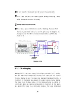
Connect the test leads to the terminals as shown in
Figure 3-2
.
2
Set REConnect the input signal as the following figure.
3
Set threshold resistance via pressing CONT buttons. (Or
skip this step if default resistance is to be used) When ready, press
40

