


DPX16: Instructions for Basic Operation and Installation
Page 10
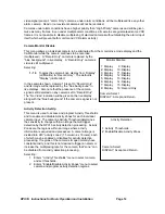
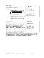
Time & Date Display Options
This menu determines the display behavior of the date and
time information for both the VCR and monitor camera
displays.
Selecting:
1.
Toggles the time and date display location through
any one of the four display quadrants for live camera
displays.
2.
Toggles the time and date for the monitor display
ON/OFF.
3.
Toggles the time and date for the VCR display
ON/OFF.
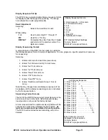
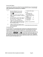
VCR Set Up
Selecting:
1.
Enters the “VCR Selection” menu for setting of a
particular make and model of VCR.
2.
Toggles the VCR record time format through up to 8
possible settings plus “Cam Sw Input” for the
selected VCR. The default value is 24 Hour format.
Note that if the “Cam Sw Input” is used, it must
be selected for both the VCR and Alarm
recording formats.
3.
Toggles the VCR record time format as in #2 above
for an alarm condition. If the value chosen is
different from the “VCR Format”, the VCR must be
wired to the multiplexer’s alarm output so that it
changes to the recording rate selected under an
alarm condition. The default value is 2 Hour format.
4.
Toggles the VCR Video Input between “Composite”
(BNC) and “S-Video” (DIN) input signal formats. The default is “Composite”.
5.
Enters “Advanced VCR options” menu for customization of the delay table, video format, and
playback discriminator functions. See the “Advanced VCR options” menu on page 20.
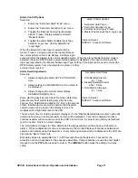
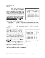
VCR Selection
Selecting:
1 - 9
Selects a particular VCR from the displayed list.
The first two entries are for standard 12 and 24
hour steps which will accommodate most VCRs.
“Standard 12 Hr steps” is the factory default.
PIP Pages the list forward for more selections. The
display will cycle back to the first page after the
last page is reached.
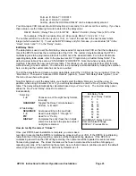
If your VCR is not on the list, use a “Standard steps”
selection. For time settings which are a multiple of 12 hours
(2, 12, 24, etc.), use the Standard 12 Hour steps. If time
settings are a multiple of 24 hours (2, 24, 48, etc.), use the
Standard 24 Hour steps. If your VCR settings do not
correspond with the either the 12 or 24 Hour Standard steps,
refer to the section “What to do if your VCR is not on the supported list” (page 22).
VCR Selection
Current VCR: Standard 12Hr steps
1: Standard 12Hr steps
2: Standard 24Hr steps
3: Custom Delay Table
4: Atsutsa TL VCR251
5: Atsutsa TL VCR964
6: Chugai CTR-024NC
7: Gyyr 1400
8: Gyyr 1550X
9: Gyyr 2051X Long
Camera 1-9: Select VCR
PIP: Next Page
DISPLAY: Previous Menu
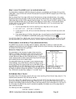
Other Display Options
1: Location Lower Right
2: Display On
3: VCR On
Camera: Select
Location is fixed in 4x4 and 3x3.
DISPLAY: Accept and Return
VCR Set up
Current VCR: Standard 12Hr steps
1: VCR Selection . . .
2: VCR Format: 24 Hr
3: VCR Alarm Format: 2 Hr
4: VCR Video Input: Composite
5: Advanced VCR options . . .
PIP: Restore Default Settings
Camera: Select
DISPLAY: Accept and Return


