6
8.
Additional ducting can be used to maintain correct static pressure or
as desired.
AIR FLOW CHECK
Appliances are tested to a temperature rise as specified on the Rating
Plate. After installation of the furnace and duct system is completed,
adjustments must be made to obtain a temperature rise as specified on
the Rating Plate.
The table below is used as reference to maintain maximum operation of
the appliance. If checking temperature rise is not possible, air flow
measurements at each registers added together and divide the opening
used from the furnace will give you air flow reading. This reading should
not be less than the minimum in the table under your BTU appliance
size.
If readings are below table values, air flow can be improved by adding
ductwork. Check to make sure restrictions in the system are not present.
16,000
20,000
25,000
30,000
35,000
1550*
1550*
1700*
1700*
1850*
*FPM= feet per minute readings
WARNING
FIRE OR EXPLOSION
Never check for leaks with an open flame. Turn on the gas and apply
soapy water to all joints to see if bubbles are formed.
PROPANE GAS CONNECTION
1.
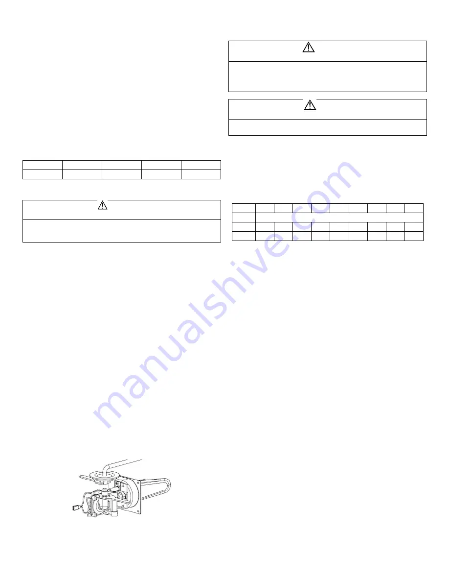
Connect gas line to the fitting located on top right side of furnace or if is
supplied with an extended manifold at the rear of the furnace.
2.
Be sure all male pipe threads, other than flare fittings, are treated with a
sealing compound resistant to the action of propane (LP) gas. DO NOT
put sealing compound on flare fittings.
3.
Use two wrenches to hold nut when tightening gas lines. DO NOT twist
valve assembly.
A 1/8” N.P.T. plug is accessible for test gauge connection on gas valve
assembly for pressure testing.
A 3/8” flared fitting connection provided at gas control valve inlet for gas
supply connection to furnace. The gas supply line of the furnace must be
of adequate size to provide 11” W.C. gas pressure. This pressure to be
maintained under maximum flow conditions with all gas appliances in
operation.
If local codes allow the use of a flexible gas appliance connector, always
use a new listed connector. Do not use a connector, which has
previously serviced another gas appliance.
1.
Remove grommet plug from furnace.
2.
Insert gas line through grommet plug (DO NOT CUT).
3.
Connect gas line inside furnace casing immediately ahead of gas
control valve.
4.
Connect gas line to brass fitting located on top or right side of
furnace.
5.
Some models will have fittings at the rear outside of the casing.
6.
Use two wrenches to hold brass fitting and flare nut when tightening
gas line to brass fitting. DO NOT twist valve assembly
Figure 7
ELECTRICAL CONNECTIONS
WARNING
INJURY OR PROPERTY DAMAGE
Label all wires before disconnecting for servicing. Wiring errors can
cause improper and dangerous operation. Verify proper operation after
servicing.
Disconnect electrical power before servicing.
CAUTION
PROPERTY DAMAGE
This connection is for low-voltage battery or direct current only.
Do not connect to 120 or 240 volts AC.
POWER SUPPLY
Atwood Mobile Products highly recommends the use of an electronic
(solid state) converter with clean power output. This will assure the life of
the electronic controls and motor life could be extended beyond typical
linear converter applications.
Conductor Sizing Table
– Maximum 10% Voltage Drop – (12VDC)
Current draw (AMPS)
Amps
3
4
5
6
7
8
9
10
15
Gage
Max. Length of SAE conductor (in feet) from source to device
18
57
43
34
29
25
21
19
17
11
16
87
65
52
43
37
33
29
26
17
This furnace is designed for negative ground 12 volts DC only. DO
NOT attempt to alter furnace for a positive ground system or
connect the furnace directly to 120 volts AC. Damage to furnace
components will occur and warranty will be voided.
Use a minimum of 18 GA wire to minimize voltage drop. Furnace
must be installed so electrical components are protected from
water. To make electrical connections see wiring diagrams.
For best furnace performance when power supply is from a
converter equipped with a charging port, wire converter to furnace
parallel with battery. This provides consistent voltage to furnace,
increasing component life, filtering power surges and AC spikes.
All units are supplied with a power switch which when turned off
during servicing will remove power through furnace wiring. Switch
must be in the ON position for furnace to operate.
The direct high voltage spark ignition generates a radio frequency
that could cause interference with other microprocessor-based
equipment. Locate equipment at least five feet (5’) from furnace
location. If this distance cannot be maintained a shielded high
voltage lead can be used.
1.
Route wiring to top of furnace.
2.
Connect red wire to positive side of power supply.
3.
Connect black wire to grounded side of power supply.
4.
Connect blue wire marked positive thermostat to + side wire of
thermostat using 22-18 GA stranded wire.
5.
Connect other blue wire to the other thermostat lead-using minimum
22-18 GA stranded wire.
THERMOSTAT INSTALLATION
Thermostats are not supplied. To purchase a thermostat rated for
12VDC or 24VAC, Minimum 1 AMP rating, they can be ordered
through Atwood.
Be sure all electrical power has been disconnected from the air
conditioner, furnace, and the power supply.
The thermostats are very sensitive. HANDLE WITH CARE AT ALL
TIMES.
Pick a dry area where air circulation is good.
Do not install the thermostat where there are unusual heating
conditions: such as direct sunlight, heat producing appliances
(television, radio, wall lamp, etc.) or a furnace or air conditioner
output registers.
Summary of Contents for AFMD16
Page 8: ...8 WIRING AND LADDER DIAGRAM ...
Page 9: ...9 PART DRAWINGS PART LISTS ...
Page 10: ...10 ...
Page 11: ...11 ...


